
Low Distortion IMX219 M12 Mount Camera Module for Raspberry Pi - Datasheet
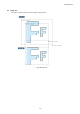
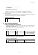
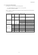
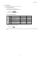
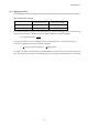
Table Of Contents
- Description
- Features
- Device Structure
- USE RESTRICTION NOTICE
- 1. Block Diagram and Pin Configuration
- 2. Pixel Signal Output Specifications
- 3. Control Registers
- 3-1 2-wire Serial Communication Operation Specifications
- 3-2 2-wire Serial Communication Register Map (Configuration register, Parameter limit register)
- 3-3 Parameter Limit Registers – [0x1000-0x1FFF] (Read Only and Static)
- 3-4 Manufacturer Specific Registers – [0x3000-0x5FFF ]
- 3-5 Frame Bank A and Bank B specific output samples
- 4. Output Data Format
- 6. On Chip Image Processing
- 7. NVM Memory Map
- 8. How to operate IMX219PQH5-C
- 9. Other Functions
- 10. Electrical Characteristics
- 11. Spectral Sensitivity Characteristic
- 12. Image Sensor Characteristics
- 13. Measurement Method for Image Sensor Characteristics
- 14. Spot Pixel Specification
- 15. Notice on White Pixels Specifications
- 16. Chief Ray Angle Characteristics
- 17. Connection Example
- 18. Notes On Handling

IMX219PQH5-C
56
5-5 Frame Rate Calculation Formula
Frame rate in all-pixel scan mode is calculated by the followings.
[ In the case of (frame_length_lines - 4 > coarse_integration_time) ]: Frame_Length = frame_length_lines
[ In the case of (frame_length_lines - 4 < coarse_integration_time) ]: Frame_Length = coarse_integration_time + 4
5-6 Black Level Control
The IMX219PQH5-C has a stable black level clamp function. The average value of the black level is adjusted to 64d.
When selecting output format RAW8, Black level in the table below is divided by 4.
Table 18 Gain Setting Variables
CCI
Black Level (dec)
64 (Fixed) RAW10, COMP8
16 (Fixed) RAW8
5-7 Storage Time (Electronic Shutter) Settings
5-7-1 Storage Time (Electronic Shutter) Setting Registers
The storage time setting registers are shown below. The value of the register, coarse_integration_time, indicates
the number of lines for the storage time.
The maximum storage time value in normal frame rate mode 4number of
lines per frame (set by frame_length_lines) including the blanking period.
Table 19 Storage Time Setting Register
CCI
registers
Register name
Address
Setting value (dec)
Remarks
coarse_integration_time
0x015A
0x015B
0x025A
0x025B
1 to frame_length_lines-4
0x015A = coarse_integration_time_A[15:8]
0x015B = coarse_integration_time_A[7:0]
0x025A = coarse_integration_time_B[15:8]
0x025B = coarse_integration_time_B[7:0]
The value of the register, fine_integration_time, indicates the number of pixels for the storage time.
The register, fine_integration_time, is a fixed value, read only register.
Table 20 Storage Time Offset Register
CCI
registers
Register name
Address
Setting value (dec)
Remarks
fine_integration_time
0x0388
0x0389
500
RO register