
Low Distortion IMX219 M12 Mount Camera Module for Raspberry Pi - Datasheet
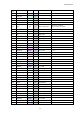


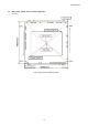
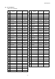
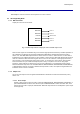
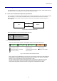
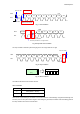
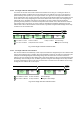
Table Of Contents
- Description
- Features
- Device Structure
- USE RESTRICTION NOTICE
- 1. Block Diagram and Pin Configuration
- 2. Pixel Signal Output Specifications
- 3. Control Registers
- 3-1 2-wire Serial Communication Operation Specifications
- 3-2 2-wire Serial Communication Register Map (Configuration register, Parameter limit register)
- 3-3 Parameter Limit Registers – [0x1000-0x1FFF] (Read Only and Static)
- 3-4 Manufacturer Specific Registers – [0x3000-0x5FFF ]
- 3-5 Frame Bank A and Bank B specific output samples
- 4. Output Data Format
- 6. On Chip Image Processing
- 7. NVM Memory Map
- 8. How to operate IMX219PQH5-C
- 9. Other Functions
- 10. Electrical Characteristics
- 11. Spectral Sensitivity Characteristic
- 12. Image Sensor Characteristics
- 13. Measurement Method for Image Sensor Characteristics
- 14. Spot Pixel Specification
- 15. Notice on White Pixels Specifications
- 16. Chief Ray Angle Characteristics
- 17. Connection Example
- 18. Notes On Handling

IMX219PQH5-C
17
3. Control Registers
The IMX219PQH5-C can use the 2-wire serial communication method for sensor control. These specifications are
described for sensor control using the 2-wire serial communication as follows.
3-1 2-wire Serial Communication Operation Specifications
The 2-wire serial communication method conforms to the Camera Control Instance (CCI). CCI is an I2C fast-mode
plus ( INCK[fSCK] = 11.4 to 27 MHz) compatible interface, and the data transfer protocol is I2C standard.
This 2-wire serial communication circuit can be used to access the control-registers and status-registers of
IMX219PQH5-C.
Fig. 5 2-wire Serial Communication
Table 3 Description of 2-wire Serial Communication Pins
Symbol
Description
SDA
Serial data communication
SCL
Serial clock input
3-1-1 Communication Protocol
2-wire serial communication supports a 16-bit register address and 8-bit data message type.
Slave Address
[7:1]
R
/
W
AS
Register Address
[15:8]
A
Register Address
[7:0]
A
Data
[7:0]
A
/
A
P
From Master to Slave
Direction Dependent on Operation
From Slave to Master
S=Start Condition
P=Stop Condition
(Sr=Repeated Start Condition)
A=Acknowledge
A=Negative Acknowledge
Fig. 6 2-wire Serial Communication Protocol
Data is transferred serially, MSB first in 8-bit units. After each data byte is transferred, A (Acknowledge)/
(Acknowledge) is transferred. Data (SDA) is transferred at the clock (SCL) cycle. SDA can change only
while SCL is Low, so the SDA value must be held while SCL is High.
The Start condition is defined by SDA changing from High to Low while SCL is High. When the Stop
condition is not generated in the previous communication phase and Start condition for the next
communication is generated, that Start condition is recognized as a Repeated Start condition.
Master IMX149
SCL
SDA
IMX219