
User's Manual

5634RCS User’s Manual
63
Appendix C provides RS-232C technical information for the modem.
C.1 RS-232C Connector
The modem provides a DTE interface via a 25-pin female (DB-25s) connector that
conforms to the EIA RS-232C standard. The connector is labeled RS-232 and located on
the back of the modem ( see Figure B-1).
PHONE
LINE JACK
ON OFF
AC 9V RS2
32
LINE PHONE
Figure B-1 DB25 connector on the modem back panel
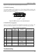
C.2 RS-232C Pin Assignments
Table B-1 summarizes the RS-232C pin assignments that pertain to the modem. Your
cable must provide these signals for your computer to communicate with your modem.
Table C-1. RS-232C pin assignments
Pin Abbreviation V.24
Designation
Function Signal Direction
2 TXD 103 Transmit Data To modem
3 RXD 104 Receive Data From modem
4 RTS 105 Request to Send To modem
5 CTS 106 Clear to Send From modem
6 DSR 107 Data Set Ready From modem
7 102 Signal Ground Common
8 DCD 109 Received Line
Signal Detector
From modem
15* TXCLK 114 Transmit Clock From modem
17* RXCLK 115 Receive Clock From modem
20 DTR 108 Data Terminal
Ready
To modem
22 RI 125 Ring Indicator From modem
24* XTCLK 113 External Serial
Clock Transmit
To modem
* These signals are used during synchronous operation only.
T
T
r
r
o
o
u
u
b
b
l
l
e
e
s
s
h
h
o
o
o
o
t
t
i
i
n
n
g
g