5634RCS User’s Manual Congratulations on purchasing the most sophisticated modem available. Your modem combines advanced technology with state-of-the-art features to bring you the modern advanced communications device available today! This modem provides the following features. n Modem Capabilities K56Flex, V.90, 56000bps, 33600bps, 31200bps ¨ ITU-T V.34, V.32bis, V.32, V.23, V.22bis, V.22, V.21, Bell 212A, and 103 ¨ V.42LAPM and MNP 2-4, and MNP 10 error correction ¨ V.
5634RCS User’s Manual Table of Contents CHAPTER 1 INSTALLING THE MODEM.............................................................4 1.1 CHECKING YOUR COMPONENTS .................................................................................................4 1.2 WHAT ELSE YOU NEED .............................................................................................................4 1.3 INSTALLING THE MODEM ...........................................................................................
5634RCS User’s Manual 6.1 READING AN S-REGISTER VALUE ...............................................................................................33 6.2 CHANGING AN S-REGISTER VALUE.............................................................................................33 6.3 S-REGISTER DESCRIPTIONS......................................................................................................33 CHAPTER 7 HARDWARE QUICK INSTALLATION GUIDE ................................51 7.1 FOR WINDOWS 95 .
5634RCS User’s Manual Chapter 1 Installing the modem This installation guide provides detailed instructions for installing your modem with computer or terminal. 1.
634RCS User’s Manual l l An RS-232-C cable with at least one male connector for connecting to your modem; Your computer's requirements determine the gender of the connector on the other end. Software that lets the modem communicates with your computer. If you lack any of these items, refer to your computer reference manual or contact your computer dealer. If your computer does not have an RS-232C DB25 connector, obtain an adapter cable from your computer dealer. 1.
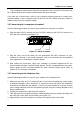
5634RCS User’s Manual 1.7 Connecting to your telephone Your modem is so convenient. It provides a second modular telephone jack that lets you connect your telephone to the same telephone line the modem is using. This lets you manually dial data calls or make voice calls when you are not using your modem. Use the following procedure to connect your telephone to your modem: 1. 2. Connect the telephone's modular cord into the PHONE jack on the back of your modem (see figure 1-1).
5634RCS User’s Manual ON OFF POWER PHONE JACK COMPUTER CONNECTOR LINE JACK Figure 1-3. Completed modem installation If you connected the modem to a computer, place the computer into terminal mode and complete the configuration information required by the software. Refer to your software manual to find out which commands to use. Then use the following procedure to verify your modem connections: 1. Type AT and press the Enter key. The RD and TD LEDs flash on the modem front panel.
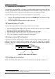
5634RCS User’s Manual l If you want to turn off your modem, set the POWER switch on the back of the modem to the OFF position. 1.11 Modem LEDs The modem has 9 front panel LEDs, which keep you constantly informed of the modem's status. Figure 1-4 shows the LEDs. TR MR TD RD OH AA CT S RT S CD C MI Figure 1-4. Top panel of modem LED AA CTS RTS CD OH RD TD 8 Meaning AA is Auto-Answer LED. This LED goes ON when the modem is set up to auto-answer incoming calls CTS is the Clear To Send LED.
5634RCS User’s Manual LED TR MR Meaning TR is the Data Terminal Ready LED. This LED goes ON when the modem is receiving a Data Terminal Ready (DTR) signal from your computer. Your computer sends this sign al when the computer is ready to send or receive data ( DTR is ON ). This LED does not work with Macintosh, which uses the DTR signal for hardware flow control purposes. MR is the Modem Ready LED, This LED goes ON when your modem is connected to an AC outlet and turned on.
5634RCS User’s Manual Chapter 2 Typing commands and receiving responses Chapter 2 describes the format to use when typing modem commands. Chapter 2 also describes the responses that your modem sends to your computer screen when you execute, or try to execute, modem commands. If you will be using a communication software program to make data calls, you will probably not need to type commands, because your software program will handle these tasks for you.
5634RCS User’s Manual 2.5 Typing more than 40 characters If you want to type more than 40 characters on a command line, type a regular command line (up to 40 characters long) and end it with a semicolon as the last character. When you press Enter, your modem executes the commands and returns to command mode, so you can type your next command line. 2.6 Omitting a parameter Some commands require a numeric parameter such as 0,1, or 2.
5634RCS User’s Manual program to make data calls, you may not see these responses because your software program will probably intercept the responses. Response sets Modem responses can come from one of five response sets. These response sets are designed X0, X1, X2, X3, and X4. The response sets determine which modem responses are sent by the modem. They also define certain dialing characteristics and how the modem handles dial tones and busy signals, as described in the following sections. 2.
5634RCS User’s Manual When you send a Dial command with this response set in effect, your modem will listen for a dial tone before dialing. If it does not detect a dial tone within five seconds, it hangs up and returns the NO DIALTONE response. 2.9.4 X3 response set The X3 response set consists of all responses in Table 2-1, except NO DIALTONE. When this response set is in effect and you send a Dial command to your modem, your modem will blind dial the call.
5634RCS User’s Manual Word Response OK CONNECT RING NO CARRIER ERROR CONNECT 1200 NO DIALTONE BUSY NO ANSWER CONNECT 600 CONNECT 2400 CONNECT 4800 CONNECT 9600 CONNECT 7200 CONNECT 12000 CONNECT 14400 CONNECT 19200 CONNECT 38400 CONNECT 57600 14 Table 2-1. Modem responses Number Meaning Response 00 Modem successfully executed a command line. 01 If X0 is in effect, modem made a data connection at 0-300,1200, 2400, 9600, 19200bps, Otherwise modem made a data connection at 0-300 bps.
5634RCS User’s Manual CONNECT 115200 19 Modem made 115.2kbps.
5634RCS User’s Manual Word Response CONNECT 75TX/1200RX CONNECT 1200TX/75RX DELAYED Number Response 22 Meaning BLACKLISTED 32 FAX DATA 33 35 CARRIER 300 CARRIER 1200/75 CARRIER 75/1200 CARRIER 1200 CARRIER 2400 CARRIER 4800 CARRIER 7200 CARRIER 9600 CARRIER 12000 CARRIER 14400 CARRIER 16800 CARRIER 19200 CARRIER 21600 CARRIER 24000 CARRIER 26400 CARRIER 28800 CONNECT 16800 CONNECT 21600 CONNECT 24000 CONNECT 26400 CONNECT 28800 40 44 Modem made a data connection at 75bps transmit and 1200bps receiv
5634RCS User’s Manual Word Response COMPRESSION: CLASS 5 COMPRESSION: V.
5634RCS User’s Manual Word Response CONNECT 44000 CONNECT 46000 CONNECT 48000 CONNECT 50000 CONNECT 52000 CONNECT 54000 CONNECT 56000 * ** 18 Number Response 171 172 173 174 175 176 177 Meaning Modem made 44000bps. Modem made 46000bps. Modem made 48000bps. Modem made 50000bps. Modem made 52000bps. Modem made 54000bps. Modem made 56000bps.
5634RCS User’s Manual Chapter 3 Using configuration profiles Your modem is preset so that you can begin transferring data files as soon as you install the modem and load your communication software. If you dialing and answering requirements do not match the modem's default configuration profile, you can create your own profiles and store them safely in your modem's nonvolatile memory. The profiles will be saved, even when you turn off your modem.
5634RCS User’s Manual 1. Press the Enter key. The next time you turn on or reset your modem, it will drive its operating characteristics from Profile 0. 2. To recall Profile 1 instead of Profile 0, type AT&Y1 instead of AT&Y0. 3.3 Reset and recalling profile If you prefer, you can use ATZn command to reset the modem and load a stored configuration profile : For example, to reset your modem and recall Profile 0 : 1. 2. Type ATZ0 Press the Enter key. Returning to the default profile 1.
5634RCS User’s Manual Setting Speaker status Speaker volume Test timer setting Wait for carrier after dialing Wait for dial tone Wait for dial tone before dialing Default On, but off when carrier detected Medium 0 second 50 seconds 2 seconds Enabled Obtained from Memory Yes Yes Yes Yes No Yes 21
5634RCS User’s Manual Chapter 4 Error correction and data compression Your modem supports sophisticated MNP 1- 4 and V.42 error- correcting protocols. These protocols ensure the transmission of error-free data − even over noisy, error- prone telephone lines. Your modem also supports the V.42bis and MNP 5 data-compression protocols, which maximizes data throughput and significantly reduces the time needed to exchange data. 4.
5634RCS User’s Manual 4.4 Configuring for reliable operation To communicate with remote MNP modems only: 1. Type AT\N5 2. Press the Enter key. Your modem responds with OK. When your modem originates or answers calls, it will try to make an MNP connection. If that fails, your modem will hang up and return to command mode. To communicate with remote V.42 modems only: 1. Type AT\N4 2. Press the Enter key. Your modem responds with OK. When your modem originates or answers calls, it will try to make a V.42/V.
5634RCS User’s Manual Chapter 5 List of modem commands Chapter 5 describes the modem commands available to your modem. If you will be using a data communication software program to send and receive files, you will probably not need to use these commands, because your software program will handle these tasks for you. However, if you want to bypass your communication software program and perform modem tasks directly with your modem, you will find the commands described in this chapter helpful.
5634RCS User’s Manual Modem Description Commands 1 Return OK message. Cn D Dial command Puts the modem into the originate mode, allowing it to automatically dial a telephone number. The telephone number to be dialed, the symbols # and * and the dial modifiers P, R, S=n, T, W, @, !, ; and, can follow the D command.
5634RCS User’s Manual Modem Description Commands On RETURN to data mode after using escape characters to switch to command node 0 Return to data mode 1 Perform equalizer retrain sequence, then return to data mode. A retrain causes the modem to optimize its operating characteristics to obtain the best data transmission. This command works at speeds of 2400bps or faster. Qn Modem responses Determines whether the modem returns responses after you execute, or try to execute, a modem command.
5634RCS User’s Manual Modem Description Commands Wn Negotiation process responses Responses that report the carrier speed of the remote modem, the error-correction protocol used, and the data compression method used(if any). Modem responses are described in Chapter 2. 0 CONNECT responses show DTE speed, and disable all extended responses. (default) 1 CONNECT responses show DTE speed, and enable CARRIER and PROTOCOL extended responses. 2 CONNECT responses show DCE speed, and disable all extended responses.
5634RCS User’s Manual Modem Description Commands &Fn Fetch the factory default 0 Fetch the factory configuration 0 1 Fetch the factory configuration 1 &Gn Guard tones Guard tones are used internationally, but are not used in the USA. 0 Disabled (default) 1 Generate 550Hz guard tone 2 Generate 1800Hz guard tone &Jn Telephone Jack Control This command is only included for compatibility and performs no function except to load the S-Register.
5634RCS User’s Manual Modem Description Commands &Rn Clear to send signal status Controls the Clear To Send (CTS) signal during synchronous operation. During asynchronous command and Data Modes, CTS is always ON. 0 CTS signal tracks the Request To Send (RTS) signal (default) 1 Modem ignores RTS and keeps CTS active continuously, regardless of RTS status. &Sn Data Set Ready signal status 0 DSR signal always ON (default) 1 DSR signal is ON during handshaking and OFF in test or idle mode.
5634RCS User’s Manual MNP/ V.42/V.42bis Commands %Cn %En %L %Q %7 %8 \Bn \Gn \Kn 30 stores in memory position 0 the telephone number 1 818 555 2121, which will be Touch Tone (T) dialed. Table 5-2. MNP/V.42/V.42bis commands Description Enable/disable MNP Class 5 data compression 0 Disable data compression 1 Enable MNP 5 data compression 2 Enable V.42bis data compression 3 Enable both V.42bis and MNP 5 data compression.
5634RCS User’s Manual In Data Mode; if reliable mode, send break to the remote system \K0,\K2,\K4 Enter Command Mode, don't send break to remote modem \K1 Modem clears modem and terminal buffers, and sends break to remote system \K3 Modem does not clear terminal and modem buffers, and sends break to remote modem \K5 Modem sends break to remote modem in sequence with any transmitted data In Command Mode; if reliable mode, send break to the remote system \K0 or \K1 Modem clears modem and terminal buffers, an
5634RCS User’s Manual MNP 10 Commands -Kn -SEC=n 32 Table 5-3. MNP 10 commands Description MNP extended service This command enables or disables conversion of a V.42 LAPM connection to an MNP 10 connection. 0 Disables V.42 LAPM to MNP 10 conversion. (default) 1 Enables V.42 LAPM to MNP 10 conversion 2 Enables V.42 LAPM to MNP 10 conversion; inhibits MNP extended services initiation during V.
5634RCS User’s Manual Chapter 6 List of modem S-register Your modem has S-registers that affect various operating characteristics, let you obtain information about the modem, and let you test the modem. Each S-Register has a factoryset value, which you can read or change to fit your particular requirements. Chapter 6 explains how to read and change S-Register repeatedly. A sequential list of S-Register is also provided. 6.1 Reading an S-Register value To read the current value of an S-Register : 1.
5634RCS User’s Manual Table 6-1 S-Register description Default Description SRegister S0 Range 0-255 rings 0 S1 0-255 rings 0 S2 0-255, ASCII 43 (+) S3 0-127, ASCII 13 (Carriage Return) S4 0-127, ASCII 10 (Line Feed) 34 Auto-answer Assigning a value from 1 to 255 in Register S0 tells the modem how many rings must occur before it can auto-answers calls. The default, 0, turns off the auto-answer feature.
5634RCS User’s Manual SRegister S5 S6 S7 S8 S9 Range Default Description 0-32 , ASCII 8 Backspace character. (Backspace) Register S5 sets the ASCII value of the backspace character is the one created by passing the Backspace key and the character echoed to move the cursor to the left. To change this value, assign an ASCII value between 0 and 32 or greater than 127. Do not use values between 33 and 126 since they correspond to printable ASCII characters.
5634RCS User’s Manual signal or voice foe carrier signal.
5634RCS User’s Manual SRegister S10 Range Default Description 1-255 tenths of a second 14 S11 50-255 ms 95 S12 0-255 1/50 seconds 50 Carrier loss time Register S10 sets the time between the loss of a remote modem's carrier signal and when the modem disconnects. This allows the remote modem's carrier signal to momentarily disappear from the telephone line without the modem disconnecting. Touch-Tone speed Register S11 controls the speed of the Touch-Tone (DTMF) dialing.
5634RCS User’s Manual SRegister S14 S16 38 Range Default Description General Bit Mapped Options Status Bit 0¡ Ð This bit is ignored.
5634RCS User’s Manual SRegister S18 Range Default Description 0-255 seconds 0 S19 Bit Mapped 0, hex S20 0 - 255 0 Test Timer Register S18 sets the amount of time for modem tests. The tests can run from 1 to 255 seconds, depending on the value in S18. The factory setting turns off the timer. If the command &T0 is used to end the modem tests, the value of S18 can be set to 0 to turn off the test timer. AutoSync Bit Mapped Options Defines the options for AutoSync operation .
5634RCS User’s Manual SRegister S21 Range S22 117 40 Default Description 4 24/General Bit Mapped Options Status Indicates the status of command options. Bit 0¡ Ð Set by &Jn command but ignored otherwise. Bit 2¡ Ð CTS behavior(&Rn) 0= CTS tracks RTS (&R0) 1= CTS always on (&R1) (Default) Bit 3-4¡ Ð DTR behavior(&Dn) 0= &D0 selected (Default) . 1= &D1 selected . 2= &D2 selected 3= &D3 selected Bit 5¡ Ð RSLD(DCD) behavior(&Cn) 0= &C0 selected (Default) .
5634RCS User’s Manual SRegister S23 Range Default Description 62 General Bit Mapped Options Status Indicates the status of command options Bits 1¡ Ð Grant RDL 0=RDL not allowed (&T5) (Default) 1=RDL allowed(&T4) ¡ Ð Bits 1-3 DTE Rate 0= 0-300 bps 1= 600 bps 2= 1200 bps 3= 2400 bps 4= 4800 bps 5= 9600 bps 6= 19200 bps 7=38400 bps or higher (Default) Bits 4-5¡ Ð Assumed DTE parity 0= even 1= not used 2= odd 3= none (Default) Bits 6-7¡ Ð Guard tone (&Gn) 0= None(&G0) (Default) 1= None (&G1) 2= 1800 Hz (&
5634RCS User’s Manual SRegister S27 S28 42 Range Default Description 73 Bit Mapped Options Status Indicates the status of command options Bits 0,1,3 Synchronous /asynchronous selection (&Mn/&Qn) 3 1 0 0 0 0 = &M0 or &Q0 0 0 1 = &M1 or &Q1 0 1 0 = &M2 or &Q2 0 1 1 = &M3 or &Q3 1 0 0 = &Q4 1 0 1 = &Q5 (Default) 1 1 0 = &Q6 Bit 2 Leased line control (&Ln) 0 = Dial up line (&L0)(Deault) Bits 4-5 Internal clock select (&Xn) 0=Internal clock (&X0) (Default) 1 = External clock (&X1) 2 = Slave clock (&X2) B
5634RCS User’s Manual SRegister Range Default Description Bits 6-7 (*Hn) S29 0-255 10 ms interval 70 make/break ratio at 20 pluses per second (&P2) 3 = 33%~67% make/break ratio at 20 pluses per second (&P3) MNP Link Negotiation Speed 0 = Link negotiation at highest speed (*H0) (Default) 1 = Link negotiation at 1200 bps (*H1) 2 = Link negotiation at 4800 bps (*H2) Flash Dial modifier Time Sets the length of time, in units of 10 ms , that the modem will go on-hook when it encounters the flash (!) dia
5634RCS User’s Manual SRegister S30 Range Default Description 0-255 tens of seconds 0 (disable) Disconnect Inactivity Timer Sets the length of time , in tens of seconds, that the modem will stay online before disconnecting when no data is sent or will reset the timer. The timer is inoperative in synchronous mode. BIT Mapped Options Status Bit 0 ¡ Ð Single line connect message enable/disable(\Vn) 0=Message controlled by S95, Wn and Vn (\V0)(Default) 1= Single line connect message (\V1) ¡ Ð Bit 1 Auto l
5634RCS User’s Manual SRegister S36 S37 Range Default Description Bit Mapped Bit 0-2 07, hex LAPM Failure Control This value indicates what should happen upon a LAPM failure. 0 Modem disconnect. 1 Modem stays on-line and direct mode connection is established. 3 Modem stays on-line and a normal mode connection is established. 4 An MNP connection is attempted and if it fail, the modem disconnects. 5 An MNP connection is attempted and if it fails a direct mode connection is established.
5634RCS User’s Manual SRegister S38 S39 46 Range Default Description 0-255 seconds 20 Delay Before Forced Hang Up This register specifies the delay between the modem’s receipt of the H command to disconnect (or ON-to-OFF transition of DTR if the modem is programmed to follow the signal), and the disconnect operation. Applicable to error-correction connection only. This register can be used to ensure that data in the modem buffer is sent before the modem disconnects.
5634RCS User’s Manual SRegister S40 Range Default Description 105 (Non- General Bit Mapped Options Status NP 10 models) 107 (MNP 10 models) MNP Extended Services (-Kn) Bit 0-1 0= Disable extended services (-K0) (Default for non-MNP 10 models.) 1= Enable extended services (-K1) (Default for MNP 10 models.) 2= Enable extended services (-K2) Power Level Adjustment for Cellular Use Bit 2 ()Mn) 0= Auto-adjustment ()M0) (Default) 1= Force adjustment ()M1) Bits 3-5 Break Handling (\Kn) 0= \K0 1= \K1 2= \K2 3=
5634RCS User’s Manual SRegister S41 Range Default Description 3 General Bit Mapped Options Status Indicates the status of command options Compression selection (%Cn) Bit 0-1 0= Disabled (%C0) 1= MNP 5(%C1) 2= V.42 bis (%C2) 3= MNP 5 and V.42 bis (%C3) (Default) Auto retrain and fallback/fall forward Bit 2,6 (%En) Bit 6 Bit 2 0 0 = Retrain and fallback/fall forward disabled (%E0) (Default) 0 1 = Retrain enabled (%E1) 1 0 = Fallback/fall forward enabled (%E2) Block mode control (\Ln) Bit 4 0= Stream mod
5634RCS User’s Manual SRegister S48 Range S82 Default Description 7 V.42 Negotiation Action The V.42 negotiation process determines the capabilities of the remote modem. However, when the capabilities of the remote modem are known and negotiation is unnecessary, this process can be bypassed if so desired. S48=0 Disable negotiation; bypass the detection and negotiation phases; and proceed with LAPM. S48=7 Enable negotiation.
5634RCS User’s Manual SRegister Range Default Description transmit attenuation level change using Configure. SRegister S86 Range Default 0-255 seconds Description Call Failure Reason Code When the modem issues a NO CARRIER result code, a value is written to this SRegister to help determine the reason for the failed connection. S86 records the first event that contributes to a NO CARRIER message. The cause codes are: Normal disconnect, no error S86=0 occurred. S86=4 Loss of carrier. S86=5 V.
5634RCS User’s Manual SRegister S201 Range 0-63 Default Description Bit 0 CONNECT response shows DCE speed, not DTE speed Bit 1 Append /ARQ to CONNECT word responses when an error-correction connection is made Bit 2 Enable CARRIER nnnn response Bit 3 Enable PROTOCOL nnnn response Bit 5 Enable COMPRESSION response 58 Cellular Transmit Level This bits in this register are set by the @Mn and: En commands to support cellular connections.
5634RCS User’s Manual n Refer to Chapter 8 to continue the installation of the modem 7.2 FOR WINDOWS 3.1x or DOS Turn your computer on and go to the "C" prompt (C:\>). If you have MS-DOS 6.0, or higher, or MS-Windows 3.1x, type MSD (Microsoft Diagnostic) at "C" prompt. This will not work if you only have Windows 95, (see above section). MSD is going to give you information on your computer system. Look and see if you can locate an entry call "COM Port.
5634RCS User’s Manual OPTION 5 If you have both "03F8" and "02F8" and you do have another device using IRQ5 while you don't have any external device connected to COM2 "02F8", have COM2 "02F8" IRQ3 on your I/O card disabled. Set your modem to COM2 IRQ3 after COM2 IRQ3 has been disabled on your I/O card.
5634RCS User’s Manual This applies in general to any skipped COM Port, where 'x' is the Port Number skipped. COMxIRQ=-1 COMxBASE= {note the appropriate port address} Port Addresses COM1 = 03F8 COM3 = 03E8 COM2 = 02F8 COM4 = 02E8 Chapter 8 Windows 95 Modem Driver Installation After following the directions in our Hardware Conflict Resolution Guide, please follow these procedures to install the driver: 8.1 Install the Modem to Windows 95 1. Boot the system from Windows 95.
5634RCS User’s Manual 4. Type the name of the driver path (ie A:\W95NT40) or you can browse the folders to indicate the path that contains the drivers) then click the “OK” button. 5. Click on the “Finish” button if the displayed modem model name fits yours. 6. Insert the Windows 95 CD-ROM to let the system copy necessary files for the modem. 7. Indicate the right path for the CD-ROM (i.e. D:\Win95) or you can browse other folders that contain the OSR2 source files.
34RCS User’s Manual 8. After completed to copy the modem driver, the “Update Device Driver Wizard” will continue to complete the installation the “Wave Device for the Voice Modem” for modem. Click on the “Next” button. 9. Click on the “Other Locations…” button if the wave driver and the modem are in the same directory. 10. Type the name of the driver path (ie A:\W95NT40) or you can browse the folders to indicate the path that contains the drivers) then click the “OK” button.
5634RCS User’s Manual 11. Click on the “Finish” button. 12. Now you’ve completed to install the drivers for the modem. 8.2 Testing the installation of the modem 1. Double click the “Modem” icon in the “Control Panel”. Choose “Diagnostics”.
5634RCS User’s Manual 2. Choose “COM2 5634RCS 56K Video Ready Modem” and click on the “More Info..” button.
5634RCS User’s Manual 3. When the screen shows correct information above the modem, it means the modem can work properly under your system. 8.3 Manually Install the Modem 1. Click on the “Modem” icon twice to begin configuring its setting. Choose “Don't detect my modem; I will select it from a list.”, then click on “Have disk”. 2. Indicate the driver path such as “A:\win95” for Windows, then click on “Next” button. 3. After installing the new Windows 95 driver for your modem.
5634RCS User’s Manual Appendix A provides compliance information about your modem. A.1 FCC Notice This equipment has been tested and found to comply with the limits for a Class B digital device, pursuant to Part 15 of FCC Rules. These limits are designed to provide reasonable protection against harmful interference in a residential installation.
5634RCS User’s Manual If your equipment causes harm to the telephone network, the telephone company may discontinue your service temporarily. If possible, they will notify you in advance. But if advance notice is not practical, you will be notified as soon as possible. You will be informed of your right to file a complain with the FCC. Your telephone company may make changes in its facilities, equipments, operations or procedures that could affect the proper functioning of your equipment.
5634RCS User’s Manual This section provides recommended initialization strings for various conditions for those models that are included in this manual. Please be advised that these recommended initial strings were produced by our technicians for general usage only.
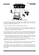
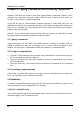
5634RCS User’s Manual Appendix C provides RS-232C technical information for the modem. C.1 RS-232C Connector The modem provides a DTE interface via a 25-pin female (DB-25s) connector that conforms to the EIA RS-232C standard. The connector is labeled RS-232 and located on the back of the modem ( see Figure B-1). ON OFF AC 9V RS232 LINE JACK LINE PHONE PHONE Figure B-1 DB25 connector on the modem back panel C.
5634RCS User’s Manual The following diagnostic diagram will illustrate some simple methods to isolate your modem problem. Refer to the flowchart in figure C-1 step by step to isolate your hardware problem. POWER ON NO Check if the MR indicator is turned on NO YES Check if the Power Adapter is O.K.