5634 PCV User’s Manual 1
Table Contents Table Contents ..........................................................................................2 Chapter 1 Installation..............................................................................3 1. 1 Checking your components ......................................................3 1. 2 What else you need..................................................................3 1. 3 Removing the computer cover..................................................3 1. 4 Inserting the modem...
Chapter 1 Installation Chapter 1 provides detailed instructions for installing your modem. 1.1 Checking your components Unpack your components and make sure you have the following items: l The modem. l A modular telephone cable to connect your modem to the telephone line. l This user's manual. l Communication software and manual. When you open your package, make sure all of the above items are included and not damaged. If you see that any components are damaged, please notify your dealer immediately. 1.
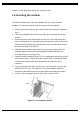
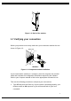
screws in a safe place and remove the computer cover. 1.4 Inserting the modem The internal modem can fit into any available PCI slot in your personal computer. To insert the internal modem in your personal computer: 1. Position yourself so that you can easily access the computer's expansion slots. 2. Select any available half-card slot into which you can install the internal modem. 3. Remove any slot cover that may be over the slot.
1.5 Connecting to the telephone line Use the following procedure to connect your modem to the telephone line: 1. Make sure you have an RJ-11 telephone jack. If you need a modular jack, either obtain a telephone adapter from a telephone or electronics store and follow the installation instructions provided with the adapter, or have your local telephone company replace your existing telephone jack with a modular-type jack and your existing telephone cord with a modular cord. 2.
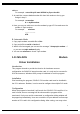
LINE PHONE 5634PCV Figure 1-2. Back of the modem 1.7 Verifying your connection Before you proceed to next step, make sure your connection matches the one shown in Figure 1-3. MODEM CARD LINE JACK LINE E PHON PHONE JACK 5634PCV Figure 1-3. Completed modem installation If you connected the modem to a computer, place the computer into terminal mode and complete the configuration information required by the software. Refer to your computer manual to find out the appropriate command to use.
If you did not receive a response, make sure your computer is sending commands to your modem. If this does not solve your problem, contact your computer dealer. 2. Use your communication software to prepare your computer to dial a call. Then type AT D x phone number, where x is either T for touch-tone dialing or P for pulse dialing and phone number is the telephone number that your modem is using.
file then hit OK. You will be presented with a listing of Topic modems. Select the model number of your modem and then hit OK. Click Finish and Windows will install the driver, and then finish booting. To check the modem installation open Control Panel and then Modems. Click on the Diagnostics tab. Click on the port which lists your modem. Click on More Info. Your modem should report back with modem information. Your modem is functioning properly. 5. 6. 1.9 Windows NT 4.0 Modem Driver Installation 1. 2.
address For example : setserial ttyS2 uart 16550A irq 5 port 0xe400 3. At path /dev, remove default modem link then link modem to the tty you assign in step 2 For example : rm modem ln –s ttyS2 modem 4. Now, you can use minicom to test the modem by type ATI3 to make sure the modem is Topic modem. For example : minicom ………………. . ATI3 B. Automatic Mode 1. Copy topic.modem excutable file to /bin 2. Copy script file rc.serial to /etc/rc.d 3.
‘ OK’ button to set the desired setting to PCI card and exit the program. If user selects ‘ Cancel’ button, the changed setting will not be effective. Please note the changed setting will not be stored and saved in PC BIOS or PCI card after PC is rebooted. When ‘ OK’ button is selected, the program will automatically test the IO port and interrupt number to see whether the PCI card can be operated normally with the desired setting.
Chaper 2 AT Commands Set AT commands are issued to DTE to control the modem's operation. AT commands can only be entered while the modem is in command mode. Except for the A/ command and the +++ escape command, all commands must be prefixed with the attention code AT. For instance, the “A” command (below) would be entered as: "ATA". Without the AT prefix, the command line cannot be executed.
Bn Communication Standard Setting This command determines ITU-T vs. Bell standard. B0 Selects ITU-T V.22 mode when the modem is at 1200 bits/s. B1 Selects Bell 212A when the modem is at 1200 bits/s (default). Result Codes: OK : n = 0, 1, 15, 16 ERROR : Otherwise Dn Dial This command instructs the modem to begin the dialing sequence. A dial string can be up to 40 characters long. Any digit or symbol (0-9, *, #, A, B, C, D) could be dialed as touch-tone digits.
hook to make the phone line busy. H0 Modem goes on-hook (default). H1 Modem goes off-hook. Result Codes: OK: n = 0, 1 ERROR: Otherwise In Request Identification Information This command displays specific product information about the modem. I0 Returns product ID code. I1 Display Firmware version and checksum on the DTE. I2 Customer Used. I3 Returns fix ID information for application software identification. “TP560 Data/Fax/Voice 56K Modem” I4 Returns firmware version for data pump. I5 Returns country code.
M1* The speaker is on until the modem detects the carrier signal. M2 The speaker is always on when modem is off-hook. M3 The speaker is on until the carrier is detected, except while dialing. Result Codes: OK n = 0, 1, 2, 3 ERROR Otherwise Nn Modulation Selection This command controls whether or not the local modem performs a negotiated handshake at connection time with the remote modem when the communication speed of the two modems is different.
Qn Result Code Control Result codes are informational messages sent from the modem and displayed on your monitor. Q0* Enables modem to send result codes to the DTE. Q1 Disables modem from sending result codes. Result Codes: OK n = 0, 1 ERROR Otherwise T Select Tone Dialing This command instructs the modem to send DTMF tones while dialing. Vn DCE Response Format This command controls whether result codes are displayed as words or their numeric equivalents. V0 Displays result codes as numeric.
Result Codes: OK n = 0, 1, 2, 3, 4, 5, 6, 7 ERROR Otherwise Zn Recall Stored Profile This command instructs the modem chip set to go on-hook and restore the profile saved by the last &W command. Z0 Reset modem and retrieve active configuration profit from stored profit 0. Z1 Reset modem and retrieve active configuration profit from stored profit 1.
&Fn Load Factory Settings This command loads the configuration stored and programmed at the factory. This operation replaces all of the command options and the S-register settings in the active configuration with factory values. &Gn V.22bis Guard Tone Control This command determines guard tone frequency and is only used in V.22 and V.22bis mode. This option is not used in North America and is for international use only. &G0* Guard tone disabled. &G1 Sets guard tone to 550 Hz. &G2 Sets guard tone to 1800 Hz.
&Rn Clear To Send Signal Select &R0 Modem turns on the Clear To Send signal when it detects the Request To Send (RTS) signal. &R1* Modem turns on Clear To Send signal. Result Codes: OK n = 0, 1 ERROR Otherwise &Sn Data Set Ready (DSR) Option This command selects DSR action. &S0* DSR always ON. &S1 DSR comes on when establishing a connection and goes off when the connection ends. Result Codes: OK n = 0, 1 ERROR Otherwise &Un Protocol Selection &U0 Select V.PCM &U1 Select V.34Bis/V.34 &U2 Select V.32Bis/V.
&Yn Select Stored Profile for Power On or Reset This command does not change the behavior of the modem but is included for compatibility with applications that issue the &Y0 command &Y0 Select stored profile 0. &Y1 Select stored profile 1. Result Codes: OK n = 0 ERROR Otherwise &Zn = x Store Telephone Number This command is used to store up to three dialing strings in the modem nonvolatile memory for later dialing.
*I3 Selects connect speed 30666bps *I4 Selects connect speed 32000bps *I5 Selects connect speed 33333bps *I6 Selects connect speed 34666bps *I7 Selects connect speed 36000bps *I8 Selects connect speed 37333bps *I9 Selects connect speed 38666bps *I10 Selects connect speed 40000bps *I11 Selects connect speed 41333bps *I12 Selects connect speed 42666bps *I13 Selects connect speed 44000bps *I14* Selects connect speed 45333bps *I15 Selects connect speed 46666bps *I16 Selects connect speed 48000bps *I17 Selects c
*NC17 Greece *NC10 Netherlands *NC7 Ireland *NC8 Italy *NC43 Japan *NC26 Namibia *NC11 Norway *NC12 Portugal *NC27 South Africa *NC13 Spain *NC14 Sweden *NC15 Switzerland *NC16 UK *NC19 Czech Republic *NC24 Poland *NC25 Russia *NC22 United States *Tn Trellis Coding Selection *T0 Disables Trellis coding *T1* Enables Trellis coding *On Transmission Level Selection *O0* Selects output level -11dBm *O1 Selects output level -12dBm *O2 Selects output level -13dBm *O3 Selects output level -14dBm *O4 Selects output
\ Nn Error Control Mode Selection This command determines the type of error control used by the modem when sending or receiving data. \ N0 Normal mode. \ N1 Direct mode. \ N2 MNP or disconnect mode. The modem attempts to connect using MN 2-4 error control procedures. If this fails, the modem disconnects. This is also known as MNP reliable mode. \ N3 MNP, or buffer. The modem attempts to connect using MNP 2-4 error control procedures. If this fails, the modem will connect in Normal modem \ N4 V.
2.
CONNECT 28800 CONNECT 31200 CONNECT 33600 (V.
2.3 S Registers Definitions S registers generally affect how the AT commands perform. Contents of the registers can be displayed or modified when the modem is in command mode. To display the value of an S register: TYPE: ATSn?, where n is the register number. PRESS: Enter To modify the value of an S register: TYPE: ATSn = r where n is the register number, and r is the new register value.
This register determines the ASCII values as the carriage return character. This character is used to end command lines and result codes. Range: 0-127, ASCII decimal Default: 13 (carriage return) Units: ASCII S4 Response Formatting Character (User Defined) This register determines the ASCII value used as the line feed character. The modem uses a line feed character in command mode when it responds to the computer.
modifier in seconds. S7 is not associated with the W dial modifier. Range: 1-255 Default: 45 Units: seconds S8 Comma Dial Modifier Time This register sets the time, in seconds, that the modem must pause when it encounters a comma (,) in the dial command string. Range: 1-255 Default: 2 Units: seconds S9 Carrier Detect Response Time Register S9 sets the time the remote modem's carrier signal must be present for the local modem to recognize it.
S12 Escape Guard Time This register sets the value (in 20 ms increments) for the required pause after the escape sequence (default 1 s). Range: 0-255 Default: 50 Units: 0.02 seconds S14 Bit-mapped Register Bit-mapped register S14 lets you control modem echo, responses, dialing method, and the original or answer mode.
S22 Bit mapped Register Bit-mapped register S22 lets you control internal speaker and the modem responses.
S25 Data Terminal Ready Delay When Modem is on-line, it will ignore a Data Terminal Ready signal lasting less than the value of this register. In this mode, the values for this register are 0 to 255 in hundredths of a second, and the default value is 0.05 seconds. If you will be entering synchronous mode after dialing asynchronously, this register determines how long the modem waits before looking for the Data Terminal Ready signal.
value to 5, and the inactivity before standby will be 5 s. This is done for compatibility with previous products which allowed time-outs down to 1 s. Range: 0, 5-255 Default: 10 S95 Bit Value Function 0,1 Mapping to ATWn 2 Mapping to AT\V 3 Mapping to ATN 4 Mapping to AT*O S96 Local Phone Status This register tells the status of the Local Phone. It is read only. 0 = local phone on-hook 1 = local phone off-hook S97 Bit Value Function 0-2 Mapping to AT\Nn 7 Mapping to AT%Cn S98 Bit Value Function 0,1 Mapping
2.4 Class 1 FAX Commands The modem chip set supports FAX commands conforming to EIA standard 578. These commands are given here with short descriptions; complete explanations are given in the standard, available from the Electronic Industry Association.
Parameters: 0, 1, 8 Default: 0 Command options: +FCLASS = 0 Select data mode. +FCLASS = 1 Select facsimile class 1. +FCLASS = 8 Select voice mode. +FTS = Stop transmission and pause +FTM = Transmit FAX Data This command causes the modem to transmit data at the modulation specified by . The following table shows the values you can enter for this command and the meaning of those values. +FTM = 3 V.21 Channel2 300 +FTM = 24 V.27ter 2400 +FTM = 48 V.27ter 4800 +FTM = 72 V.29 7200 +FTM = 96 V.
+FRM = 121 +FRM = 122 +FRM = 145 +FRM = 146 V.17 12000 V.17 (short train) 12000 V.17 14400 V.17 (short train) 14400 +FTH = Transmit HDLC Data This command causes the modem to transmit data framed in the HDLC protocol at the modulation specified by . +FTH = 3 V.21 Channel2 300 +FTH = 24 V.27ter 2400 +FTH = 48 V.27ter 4800 +FTH = 72 V.29 7200 +FTH = 96 V.29 9600 +FTH = 73 V.17 7200 +FTH = 74 V.17 (short train) 7200 +FTH = 97 V.17 9600 +FTH = 98 V.17 (short train) 9600 +FTH = 121 V.
+FLO = Flow Control Select +FLO=0 Xon/Xoff and RTS/CTS flow control Turned off +FLO=1 Xon/Xoff flow control +FLO=2 RTS/CTS flow control +FPR = Serial Port Rate 2.
sds>= 128 More aggressive ;ex.
2.
%tt4=3 : V21 Ans tx space %tt4=4 : V23 Org tx mark %tt4=5 : V23 Org tx space %tt4=6 : V23 Ans tx mark %tt4=7 : V23 Ans tx space %tt4=8 : V22 org %tt4=9 : V22bis org %tt4=10 : V22 ans (tx guard tone if &g1 or &g2) %tt4=11 : V22bis ans (tx guard tone if &g1 or &g2) %tt5= 0 : V27ter 2400 %tt5= 1 : V27ter 4800 %tt5= 2 : V29 7200 %tt5= 3 : V29 9600 %tt5= 4 : V17 7200 short train %tt5= 5 : V17 7200 long train %tt5= 6 : V17 9600 short train %tt5= 7 : V17 9600 long train %tt5= 8 : V17 12000 short train %tt5= 9 : V1