
Instruction Manual


Flex 12VRX/8VRX Standard, AB and Tandem Instruction Manual (FCC/CE)
September 2016
Page 12 of 43
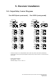
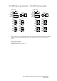
CN 11
CN 17
Fu nct ion 3
CN11
CN17
Function3
OR
4. Function Settings
4.1. Receiver
4.1.1. Output Relay Configurations
4.1.1.1. Output Relay Types
1. 2 output relays per motion – single speed only
Output relays with Forward (F) and Reverse (R) 1
st
speed only.
4.1.2. Voltage Settings
Prior to installation always check the voltage setting is correct for your application.
FUSE #
110~120VAC
220~240VAC
F3 ~ F10
5.0A
5.0A
F1 ~ F2
1.0A
1.0A
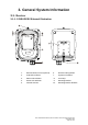
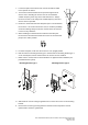
4.1.3. Indicator Light and Buzzer Installation
The miniature indicator light and buzzer can be easily
fitted onto the receiver enclosure. The indicator light or
the buzzer works simultaneously with the receiver MAIN
relays (manufacture preset). When receiver MAIN
relays are activated the indicator light or the buzzer is
also activated, or vise versa. Make sure the indicator
light or the buzzer is connected to the K30 Function
output relay CN11 port located on the AC line filter/relay
board inside the receiver. Please contact ARC
representative if you would like the indicator light or the
buzzer work differently than described above.