Model 205 Tube Welding Power Supply Operator’s Manual Part No.
M O D E L 2 0 5 O P E R A T O R ’ S M A N U A L INTRODUCTION he Model 205 is a power source and controller for automatic orbital tube welding. It is intended to be used only in conjunction with AMI or EXEL orbital tube weldheads. The Model 205 power supply provides GTAW (Gas Tungsten Arc Welding) current with pulsation controls, high frequency arc starting, purge gas controls, weldhead arc rotation and automatic timing functions.
M O D E L 2 0 5 O P E R A T O R ’ S M A N U A L Revision History Rev ECO No. Change Description Date Appr. A N/A Initial release 3/10/09 B.F. B 5355 Update sections 2.0, 3.0, 4.0, 5.0 & 6.0; delete Glossary 5/14/09 B.F. C 5411 Update section 4.10.9 Performing a Weld 07/06/09 B.F. D 5447 CE changes 12/30/09 D.C. E 5713 Correct table in Section 6.1.2 with correct weight 06/16/10 D.C. F 5817 Incorporate S/W v1.5, corrections for CE changes, add power grounded to section 2.
M O D E L 2 0 5 O P E R A T O R ’ S M A N U A L Table of Contents INTRODUCTION.................................................................................................... i NOTICE.............................................................................................................. i Revision History ............................................................................................ ii Table of Contents ...............................................................................
M O D E L 2 0 5 O P E R A T O R ’ S Chapter M A N U A L 1 1.0 SAFETY PRECAUTIONS The Model 205 is intended to be used only with AMI or EXEL weldheads for the purpose of GTAW welding of metal tube. The system is not to be used for any other purpose, specifically heating or cutting. WARNING The nature of the GTAW process creates some POTENTIAL HAZARDS. In accordance with international safety regulations the EXCLAMATION SYMBOL indicates that this equipment is considered Warning HAZARDOUS.
M O D E L 2 0 5 O P E R A T O R ’ S M A N U A L All AMI Power Supplies contain a “bleeder” circuit to ground any residual potential after welding or after an aborted or bad arc start attempt. These circuits take a few seconds to operate or could fail. The electrode should always be considered a possible shock hazard. This is especially true when the system is in “weld sequence”, ready to weld, is welding or has just finished welding.
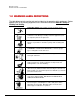
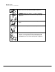
M O D E L 2 0 5 O P E R A T O R ’ S M A N U A L 1.2 WARNING LABEL DEFINITIONS The table below contains caution and warning labels for the operation of this equipment. Before operating this or any welding equipment users should be familiar with ANSI-49.1 Safety in Welding and Cutting. ELECTRIC SHOCK from welding electrode or wiring can kill. HIGH FREQUENCY RADIO WAVES can cause interference and sometimes even damage to nearby electronic equipment (such as computers) that are un-protected.
M O D E L 2 0 5 O P E R A T O R ’ S M A N U A L MOVING PARTS - Keep hands and fingers clear of fans, gears, rotors, wire feed, rotation and AVC mechanisms WARNING: AMI factory training is essential for all Welding Operators and Maintenance Technicians who operate AMI equipment. WELDING WIRE and ELECTRODES are sharp and can cause injury. MOVING PARTS may cause crush or pinch points. WARNING: Disconnect the input power to the machine before opening or servicing.
M O D E L 2 0 5 O P E R A T O R ’ S Chapter M A N U A L 2 2.0 SPECIFICATIONS These specifications pertain the to Model 205 power supply only. For weldheads, refer to the specification sheet of each particular model. For non-AMI supplied equipment such as gas tanks and regulators, refer to the original manufacturer’s documentation. The Model 205 is a mobile system that is intended be hand carried.
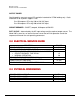
M O D E L 2 0 5 O P E R A T O R ’ S M A N U A L OUTPUT POWER Straight polarity, constant current DC regulation intended for GTAW welding only. Static characteristic of all power supplies is flat. 5 to 150 amperes DC using 100 to 120 VAC input. 5 to 150 amperes DC using 200 to 240 VAC input. CIRCUIT BREAKER – ON/OFF, two pole, 20 Ampere at 250 VAC. DUTY CYCLE – determined by the AC input voltage and the required output current.
M O D E L 2 0 5 O P E R A T O R ’ S M A N U A L 2.4 PROGRAMMABLE AND OPERATIONAL FUNCTIONS SINGLE ENTRY FUNCTIONS FUNCTION PREPURGE POSTPURGE UPSLOPE START LEVEL DOWNSLOPE LEVEL ADVANCE TRAVEL START DELAY TRAVEL DIRECTION RANGE 5.0 – 999.0 seconds 5.0 – 999.0 seconds 0.0 – 99.9 seconds 5.0 – 150.0 amps 00.0 – 99.9 seconds TIME / POSITION 00.0 – 99.9 seconds CW / CCW MULTI-LEVEL FUNCTIONS The following functions can be programmed at each level to change value during a given weld sequence.
M O D E L 2 0 5 O P E R A T O R ’ S Chapter M A N U A L 3 3.0 INITIAL SETUP This manual is intended to assist users of this equipment in set up and basic operation. It is NOT INTENDED AS A SUBSTITUTE FOR FACTORY TRAINING. 3.1 SYSTEM SYMBOLS The following symbols are present on the Model 205 version 13B050100-02 Revision NC and up: WARNING: Read this manual! This document contains information that could help prevent injury or damage to the equipment.
M O D E L 2 0 5 O P E R A T O R ’ S M A N U A L USB - USB port. Devices should not be left plugged in while welding. REMOTE - Remote control connection GROUND(+) ELECTRODE(-) - weldhead ground and electrode connections. ARC GAS OUTPUT - output for the arc shielding gas connection. WELDHEAD CONTROL - weldhead motor control. Intended for AMI and EXEL weldheads only. The optional water cooler M205-CW is marked with the following symbols: WATER RETURN - cooling water input.
M O D E L 2 0 5 O P E R A T O R ’ S M A N U A L 3.2 INSPECTION The Model 205 is shipped with a variety of peripheral equipment such as gas hoses, fittings and cables. An exact list of these items is included with each power supply shipment and should be located prior to setup. • After unpacking, inspect all items for obvious physical damage and loose parts. If damage is evident, contact a factory representative before using. If water condensation is apparent, dry the unit before using.
M O D E L 2 0 5 O P E R A T O R ’ S M A N U A L 3.3 POWER CONNECTION To avoid severe equipment damage ensure that the Model 205 power supply is connected to the correct input AC power as listed in Section 2.0 Specifications. The Model 205 can operate on any single phase voltage from 100V AC to 240V AC. Provided the input voltage is within this range, the unit will automatically adjust for the input voltage. 1. The Model 205 is supplied with a 15 foot power cord.
M O D E L 2 0 5 O P E R A T O R ’ S M A N U A L 3. The arc gas is controlled by a solenoid and flow sensor in the Model 205. Attach the input gas line to ARC GAS INPUT fitting THE WELDHEAD. on the Model 205, NOT DIRECTLY TO 4. Attach the other end of the input gas hose to the gas regulator/flow meter. Fitting it loosely by hand, tighten the nut slightly with a wrench to ensure there are no leaks. DO NOT OVER TIGHTEN. The use of plumbers tape or grease is NOT RECOMMENDED.
M O D E L 2 0 5 O P E R A T O R ’ S M A N U A L 3. Insert the two coolant line quick-disconnect fittings on the pig-tail into the mating and WATER RETURN connectors on the Model 205-CW. WATER OUT These connectors are interchangeable so either connector may be connected to either mating fitting. To prevent accidental disconnection after making the connection, finger-tighten the lock screw on the male connectors. 4.
M O D E L 2 0 5 O P E R A T O R ’ S M A N U A L 5. Insert the two coolant line quick-disconnect fittings on the adapter cable into the and WATER RETURN connectors on the Model 205mating WATER OUT CW. These connectors are interchangeable so either connector may be connected to either mating fitting. To prevent accidental disconnection after making the connection, finger-tighten the lock screw on the male connectors. 6.
M O D E L 2 0 5 O P E R A T O R ’ S M A N U A L Fig.
M O D E L 2 0 5 O P E R A T O R ’ S M A N U A L 3.6 MODEL 205 TO EXEL ROTOR DRIVER HOOK UP Always turn the power supply off before making any cable or connection changes to the power supply. The EXEL rotor driver (Model RDR-005) connects directly to the Model 205. The rotor driver has NO connections to the M205-CW Cooling Unit. 1. Attach the ground and electrode connectors on the rotor driver to their respective GROUND(+) and ELECTRODE(-) terminals on the Model 205.
M O D E L 2 0 5 O P E R A T O R ’ S M A N U A L 3.7 MODEL 205 TO M21 WELDHEAD HOOK UP Always turn the power supply off before making any cable or connection changes to the power supply. Note Note: for hook up of the M21 weldhead see the Model 21 Weldhead Operation Manual, P/N 740122.
M O D E L 2 0 5 O P E R A T O R ’ S Chapter M A N U A L 4 4.0 OPERATION Operation covers those steps that must be taken to enter a weld schedule and perform a weld. Ensure that the operator has installed the Model 205 per Section 3.0 and has a good understanding of system functions (Section 4.1). Ensure that the system is protected against dirt, dust, etc. NEVER GRIND NEAR AN EXPOSED WELDHEAD OR THE MODEL 205. Protect the system from water and liquid spray.
M O D E L 2 0 5 O P E R A T O R ’ S • M A N U A L WELD SEQUENCE AND LEVELS – A weld schedule is started by manually initiating Sequence Start. Once the sequence is started, the system operation of functions is fully automatic. A weld schedule has the ability to change values for most functions as the electrode traverses around the tube. The weld schedule is broken down into LEVELS and each level can contain a change to one or more functions. A weld schedule can contain up to 100 levels.
M O D E L 2 0 5 O P E R A T O R ’ S M A N U A L 4.2 INITIAL POWER ON Before proceeding with POWER ON it is EXTREMELY important to have a basic understanding of SYSTEM FUNCTIONS. Read Section 4.1 - System Functions before proceeding. 1. Before connecting or energizing the AC power verify that all input power set up requirements of Section 3.0 have been complied with. 2. Connect the AC power cable to the AC source and to the 115/230 VAC INPUT connector on the Model 205.
M O D E L 2 0 5 O P E R A T O R ’ S M A N U A L 4.3 SET-UP FUNCTIONS The SET UP screen is used for the initial configuration of the power supply. Use this screen to set up the following functions: Date/Time setting Password setting Language selection Language Update DATE/TIME SETTING 1. From the HOME screen press SETUP. 2. From the SETUP screen select each Date and Time field to be changed. Enter the new date and time data on the 10-key pad, then press ENTER.
M O D E L 2 0 5 O P E R A T O R ’ S M A N U A L 2. SUPERVISOR: A Supervisor may load and run any weld schedule. In addition, a Supervisor may create, change, delete, or copy a weld schedule. 3. PROGRAMMER: A Programmer has the same level of access as a Supervisor and in addition can delete or change the Operator, Supervisor and Programmer passwords, perform all Setup functions, calibrate the Model 205 and create, change or delete languages. TO SETUP A PASSWORD: 1. From the Home screen press SETUP. 2.
M O D E L 2 0 5 O P E R A T O R ’ S M A N U A L LANGUAGE UPDATE Customizing a pre-programmed language or creating a language from a pre-programmed language: 1. Insert a USB memory stick in the Model 205 USB port. 2. From the HOME screen press SETUP. 3. From the SETUP screen press ADD LANGUAGE. 4. Select a language from the list that the new language will be based on. 5. Enter the word to be changed in the textbox and press FIND (note: the search is case sensitive) 6.
M O D E L 2 0 5 O P E R A T O R ’ S M A N U A L Add a language from External Memory: 1. Insert a USB memory stick in the Model 205 USB port. 2. From the HOME screen press SETUP. 3. From the SETUP screen press ADD LANGUAGE. 4. From the ADD LANGUAGE screen press ADD LANGUAGE FROM EXT MEMORY. 5. When the Windows® Open screen displays, select the language file in the external memory to be added (*.lgv file). 6. Press OK.
M O D E L 2 0 5 O P E R A T O R ’ S M A N U A L 4.4 OPENING THE LAST WELD SCHEDULE Skip to Step 4.8 if no weld schedules are stored in the library. 1. From the HOME screen, press OPEN LAST. 4.5 SELECTING A WELD SCHEDULE FROM THE LIBRARY Skip to Step 4.8 if no weld schedules are stored in the library. 1. From the HOME screen, press LIBRARY. 2. Weld schedules will be listed from newest to oldest. Select a weld schedule then press LOAD.
M O D E L 2 0 5 O P E R A T O R ’ S M A N U A L Note Use the UP or DOWN arrows to find additional weld schedules. Note You may search for and segregate weld schedules by DIAMETER, WALL or MATERIAL. Select one or more of these categories from the 3 drop-down lists, select the weld schedule, then press LOAD. 4.6 MODIFY A WELD SCHEDULE Skip to Step 4.8 if no weld schedules are stored in the library. 1.
M O D E L 2 0 5 O P E R A T O R ’ S M A N U A L 2. From the RUN screen press SCHEDULE. 3. The first parameters displayed are the SINGLE ENTRY parameters. The MULTILEVEL parameters and ASSOCIATED DATA parameters are accessed by using the NEXT button on each screen.
M O D E L 2 0 5 O P E R A T O R ’ S M A N U A L Multi-Level Parameters: Associated Data Parameters: 4. Select each field to be modified and enter the text or value via the on-screen alphanumeric keyboard or 10-key pad, then press the RETURN or ENTER key. The changes will automatically be saved.
M O D E L 2 0 5 O P E R A T O R ’ S M A N U A L Note If the +1% or -1% button is pressed on the Multi Level screen the Primary Amps will be incremented or decremented by this percentage. This is for the purpose of ‘tweaking’ the current to improve the quality of the weld. Note Associated Data parameters are information only. Electrode Diameter, Arc Gap, Electrode Length and Part Number are calculated for M8 and M9 weldheads.
M O D E L 2 0 5 O P E R A T O R ’ S M A N U A L 4.7 COPY A WELD SCHEDULE The Model 205 has the ability to make a copy of a weld schedule and save it under a new name in the Model 205 Library. You may also copy one or all weld schedules stored in the Model 205 Library and save them to a USB Memory stick, or copy one or all weld schedules on a USB memory stick and save them to the Model 205 Library. • Copy a weld schedule in the Model 205 Library 1.
M O D E L 2 0 5 O P E R A T O R ’ S • M A N U A L View Weld Schedules Stored On a USB Stick 1. Insert a USB memory stick into the USB port on the Model 205. 2. From the HOME screen press LIBRARY. 3. From LIBRARY press VIEW USB. • Copy one or all weld schedules in the Model205 Library and save to a USB memory stick. 1. Insert a USB memory stick into the USB port on the Model 205. 2. From the HOME screen press LIBRARY. 3. Select a weld schedule to be copied and press COPY. 4.
M O D E L 2 0 5 O P E R A T O R ’ S • M A N U A L Copy one or all weld schedules from a USB memory stick to the Model 205 Library 1. Insert a USB memory stick into the USB port on the Model 205. 2. From the HOME screen press LIBRARY, then press VIEW USB. 3. Select the weld schedule to be copied and press COPY TO M205. If copying all weld schedules press COPY ALL TO M205.
M O D E L 2 0 5 O P E R A T O R ’ S M A N U A L 4.8 CREATE A WELD SCHEDULE The Model 205 provides two versions of manual weld schedule creation: Manual Multi level and Manual S3 (Single Level Sloped) and four versions of Automatic weld schedule generation: Auto Continuous Travel, Auto Stepped Travel, Auto Tack, and Auto S3. 1. From the HOME screen press CREATE NEW. 2. Enter the Weld Schedule NAME. 3. Enter the DIAMETER, WALL and, MATERIAL. 4.
M O D E L 2 0 5 O P E R A T O R ’ S M A N U A L 6. The welding parameters may now be entered manually by selecting either MANUAL MULTI or MANUAL S3, or a weld schedule may be automatically generated by selecting AUTO CONTINUOUS TRAVEL, AUTO STEPPED TRAVEL, AUTO TACK, or AUTO S3. • Manual Multi – this option allows the entry of a multi-level weld schedule. You may program up to (and not including) 100 levels. Electrode rotation can be either continuous or stepped (synchronized with current pulsation).
M O D E L 2 0 5 O P E R A T O R ’ S M A N U A L • Auto S3 – this version of automatic programming will generate a single-level program that continually ramps the current down over the course of the weld. This ramping is established by programming a starting amps (START AMPS) and an ending amps (END AMPS). • Auto-Tack – this type of auto programming creates a weld schedule for tacking.
M O D E L 2 0 5 O P E R A T O R ’ S M A N U A L If an adjustment to the weldhead’s calibration potentiometer is required the screen will display CALIBRATION FAILED – TURN TRIM POT CCW – TRY AGAIN or CALIBRATION FAILED – TURN TRIM POT CW – TRY AGAIN 4. Using the screw driver supplied with the weldhead turn the weldhead’s potentiometer a few turns in the recommended direction and re-run the calibration procedure (Steps 1 & 2). Continue these steps until the screen displays CALIBRATION COMPLETED.
M O D E L 2 0 5 O P E R A T O R ’ S M A N U A L 6. The Model 205 features a WELD/TEST button. In the TEST mode the unit will allow for electrode rotation but will not strike an arc. The WELD or TEST font on the button turns yellow to indicate which mode the system is set to. 7. When you are ready to start welding press the WELD/TEST button to put the power supply in WELD mode. 8. Press START to initiate the weld. The center of the RUN screen displays a count-down of each weld sequence.
M O D E L 2 0 5 O P E R A T O R ’ S M A N U A L 9. Once the operator manually presses the START button the following events will occur automatically: • EVENT 1: PREPURGE - welding gas will start to flow and continue to flow for the entire weld sequence from the gas source through the power supply to the weldhead. Complete gas coverage should be obtained before the arc is struck. How long it flows before the arc is struck is called the PREPURGE time. Minimum programmable time is 5 seconds.
M O D E L 2 0 5 O P E R A T O R ’ S M A N U A L Note The electrode rotation direction is a Single Entry function and cannot be programmed to change direction during a weld. • EVENT 4: LEVEL 1 and FOLLOW-ON LEVELS - at the end of TRAVEL START DELAY the program will automatically advance to Level 1 and then to follow-on levels. If programmed by DEGREES the electrode will rotate to position programmed in each level before advancing to the next level.
M O D E L 2 0 5 O P E R A T O R ’ S 4.11 • M A N U A L WELD DATA RECORDING Setup and Enable Weld Data Recording 1. Press WDR to open the Weld Data Recording screen. 2. Enter data in each of the fields Note Power Supply Model Number, Power Supply Serial Number and Weldhead Model Number are already stored in the system so these fields are automatically filled. Note The ONLY required field is Weld ID and it must be unique.
M O D E L 2 0 5 O P E R A T O R ’ S • M A N U A L Record Weld Data 1. Press RUN to return to the Weld screen. 2. Toggle WELD/TEST to WELD. Note The font on the WDR button turns yellow if Weld Data Recording is enabled AND Weld/Test is set to Weld. 3. Press START to start the weld sequence and the Weld Data Recording Note The font on the WDR button turns red while the weld data is being recorded. • Export Weld Data Record 1. Insert a USB memory stick into the USB port on the Model 205. 2.
M O D E L 2 0 5 O P E R A T O R ’ S M A N U A L 3. Press EXPORT WDR FILE to select a WDR file and an export destination. 4. Press OK Note The OK button will ONLY be enabled when BOTH the Source and Destination fields are filled. The Destination will normally be the D:\ drive which is the USB memory stick. 5. Repeat steps 3 and 4 to export additional WDR files. 6. Remove the USB memory stick and load on a PC to view / print the weld data record(s). Note The exported weld data record(s) will be in *.
M O D E L 2 0 5 O P E R A T O R ’ S Chapter M A N U A L 5 5.0 MAINTENANCE AND TROUBLE-SHOOTING Always disconnect the AC power cable from the line voltage before attempting to work with this welding power supply. 5.1 GENERAL MAINTENANCE • COOLANT - the water tank in the optional Model 205-CW cooling unit holds approximately 0.75 gallons (2.8 liters) of fluid. Check the fluid level periodically. The use of different weldheads will remove fluid from the tank over a period of time.
M O D E L 2 0 5 O P E R A T O R ’ S M A N U A L Always keep the protective boots and dust caps on all connectors and fittings until cables are ready to be installed. A major cause of downtime in any automatic welding system is improper care and use of cables. Take extreme care to avoid dropping the power supply or the weldheads. Always disconnect the power input cable from the junction box or wall-plug before cleaning.
M O D E L 2 0 5 O P E R A T O R ’ S M A N U A L 5.2 CURRENT OUTPUT CALIBRATION This procedure is intended for calibration/verification of output current by the user. True verification of current output for Quality Control purposes must be performed with a calibrated External Calibration Shunt. This shunt may be obtained from Arc Machines, Inc. (Part Number 13B072511-01). All personnel attempting to calibrate, trouble-shoot, or repair the Model 205 must be familiar with its operation.
M O D E L 2 0 5 O P E R A T O R ’ S M A N U A L PROCESS A weld schedule is required for calibration and will need to be created the first time a calibration is done. 1. Set up a Weldhead rated for 150 amps continuous duty and insert a tube, pipe, or copper rod that can withstand 150 amps of continuous current with no rotation. If these items are not available then use a Hand Torch on a large plate with the torch fixed so it cannot change the gap during calibration. 2.
M O D E L 2 0 5 O P E R A T O R ’ S M A N U A L 3. From the HOME screen press SETUP 4. From the SETUP screen press ADVANCED.
M O D E L 2 0 5 O P E R A T O R ’ S M A N U A L Note To prevent unauthorized personnel from accessing the calibration feature a temporary one-day password is required. Contact the AMI Service department for this password. You will need the Power Supply serial number displayed on the HOME screen to obtain this password. 5. Input the one-day password and press ENTER. 6. Setup the Digital Multimeter to read the 200 mVDC scale. 7.
M O D E L 2 0 5 O P E R A T O R ’ S M A N U A L 8. The START button is located in the upper right corner of the screen. Once you have determined it is safe to initiate an arc press START. After the arc is established connect the black and red test probes from the DMM to the shunt (Fig. 3). 9. The weld schedule will remain at each Command level for 15 seconds and advance through all 10 Commands. During this process make note of the DMM mV reading at each Command. 10.
M O D E L 2 0 5 O P E R A T O R ’ S M A N U A L 5.3 TROUBLESHOOTING The Model 205 has the ability to monitor certain functions. If they are not working correctly a system fault will alert the operator to the problem. SYSTEM FAULT CORRECTIONS When a System Fault occurs prior to or during welding it is required for the operator to clear the fault condition before continuing. Some faults are only temporary and the fault is corrected when the arc goes out.
M O D E L 2 0 5 O P E R A T O R ’ S M A N U A L If there is no problem with the source or with the hoses and their connections then an internal failure of the flow switch, solenoid or internal hosing is possible. Contact an AMI Service representative. • ARC VOLTS LOW or STUB OUT - this fault will only occur when an arc is present and will no longer exist when the arc goes out. If the arc voltage gets too low (below 5 volts) or the electrode should touch the weld puddle an ARC VOLT fault will occur.
M O D E L 2 0 5 O P E R A T O R ’ S Chapter M A N U A L 6 6.0 OPTIONS The following are installation and operation instructions for Model 205 options. Some options have their own manuals and these are not discussed in this section. Always turn the power supply OFF before making any cable or connection changes to the Model 205 power supply. 6.1 COOLING UNIT (Model 205-CW) SPECIFICATIONS AC INPUT POWER COOLANT CAPACITY CIRCULATION 90–260 VAC 1 Phase, 4 amps max. 0.75 gallons (2.8 liters) 0.5 GPM (2.
M O D E L 2 0 5 O P E R A T O R ’ S M A N U A L PHYSICAL CONSTRUCTION MATERIAL HEIGHT WIDTH DEPTH WEIGHT (with water) WEIGHT (without water) PUMP Aluminum cabinet/Polyethylene tank 6.25 inches (159 mm) 19.0 inches (483 mm) 14.0 inches (356 mm) 27 lbs (12.3 kg) 21.5 lbs (9.8 kg) 60 PSI (413 kPa) INSTALLATION 1. The cooling unit is shipped dry and requires 0.75 gallons (2.
M O D E L 2 0 5 O P E R A T O R ’ S M A N U A L 6.2 OPTIONAL REMOTE PENDANT • Allows for the remote START/STOP of a weld sequence, JOG of the weldhead rotor, manual gas PURGE, and return to HOME of the weldhead rotor. • Attach the remote pendant connector to the REMOTE connector on the Model 205. Note the positioning keyway and NEVER FORCE or use tools on the cable connectors. Hand-tighten the connecting ring being careful not to cross-thread the ring.
M O D E L 2 0 5 O P E R A T O R ’ S M A N U A L 55