
User Manual

5 Testing & Troubleshooting
18
5.3 Electrical Fault Diagnosis
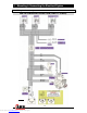
The following describes an effective procedure for tracing an electrical fault in a CKMA12 or
CKMA24 compressor which has been wired using a genuine ARB wiring loom (refer to the
diagram in Figure 7.). All steps must be performed in the order listed here for an accurate
assessment.
NOTE : Before attempting to troubleshoot a malfunctioning compressor, always
make sure that the compressor manifold has been de-pressurized, all
connections have been made according to the wiring diagram, the vehicle’s
ignition is in the ACC power position, and that the ISOLATING SWITCH has
been turned ‘ON’.
NOTE : The ‘MOTOR VOLTAGE’ referred to below should be approximately 12V in
the case of the CKMA12 and 24V in the case of the CKMA24. Otherwise
‘12V’ refers to approximately 12V regardless of compressor model as the
24V compressor runs on a 12V control circuit.
NOTE : Battery number references (e.g., [#1]) are for 24V system wiring purposes.
STEP #
Using a multimeter, check the voltage at the battery terminals to make sure the battery
is working and is fully charged. Check each individual 12V battery in a 24V system.
Did each battery measure at least 11.5 volts?
1
YES
Proceed to STEP 2.
NO
Insufficient battery voltage. Recharge or replace the battery.
Disconnect the compressor motor from the wiring loom at the connector plug. Run a
new wire directly from the negative (-) terminal of the battery [#1] to the BLK-WHT wire
of the compressor motor. Momentarily connect a wire from the positive terminal of the
battery [#2] to the RED wire of the compressor motor.
Did the compressor activate when the wires were connected?
2
YES
Remove the extra wires and reconnect the compressor motor plug.
Proceed to STEP 3.
NO
Internal compressor motor problem. Contact ARB for assistance.
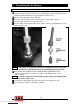
Remove the fuse from the fuse socket in the compressor wiring loom. Using a
multimeter, check the continuity (resistance) across the 2 contacts of the fuse.
Did the resistance measure less than 1 Ohm?
3
YES
Proceed to STEP 4.
NO
Blown fuse. Replace with a new 40A maxi fuse of same type. Insert new fuse with
caution in case a wiring short was responsible for the fuse blowing.
Using a multimeter, check for MOTOR VOLTAGE between a chassis ground and each
of the two contacts in the fuse socket.
Was MOTOR VOLTAGE detected at one of the two contacts?
4
YES
Reconnect the fuse into the socket. Proceed to STEP 5.
NO
Wiring fault between the positive (+) battery terminal and the fuse socket. Check the
wire connection at the battery terminal and/or replace the wiring and/or fuse socket.
Downloaded from www.Manualslib.com manuals search engine