
User Manual

4 Mounting & Connecting the Electrical System
16
4.3.2 Power Connection To A 24V Vehicle / System
NOTE : Vehicles equipped with aftermarket ‘dual battery kits’ are not classified as
24V systems. They require the 12 volt compressor kit, and connection to
the primary battery only
according to section 4.3.1.
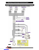
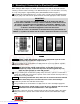
F Identify which battery in the system will be used as the 24V negative (-) terminal
(i.e., Battery #1 in the wiring diagram Fig. 7.) by connecting a multimeter across the
positive (+) terminal of one battery to the negative (-) terminal of the other battery. If you
have tested the correct negative (-) terminal then you will read approximately 24 volts on
the multimeter, and this battery will be battery #1, and the other battery with the positive
(+) terminal you have just tested will be battery #2 (refer to wiring diagram Fig. 7.).
NOTE : If you have tested the wrong negative (-) terminal then you will read
approximately 0 volts. Re-test using the opposite batteries.
F Trim the heavy gage black wire that is marked with a white stripe (BLK-WHT) for
connection to battery #1 (identified above).
NOTE : If any of the wires require extra length to reach the battery then splice in an
extension using ONLY wire that is of the same gage or bigger than the wire
being lengthened.
F Trim the RED wire and the lighter gage solid black wire with no stripe (BLK) for
connection to battery #2.
NOTE : The inline fuse should be located as close to the battery connection as
possible. Never eliminate the fuse when shortening the red wire, and only
ever lengthen the red wire on the opposite side of the fuse to the battery.
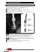
F Crimp one yellow eye terminal (supplied) onto the RED wire.
F Crimp the remaining yellow eye terminal (supplied) onto the heavy gage BLK-WHT wire.
F Crimp the blue eye terminal (supplied) onto the lighter gage black wire with no stripe
(BLK).
F Connect the BLK-WHT wire to the negative (-) terminal of battery #1 by securing the eye
terminal under the nut of the clamping bolt.
F Connect the solid black wire (BLK) to the negative (-) terminal of the battery #2 in the
same way.
F Connect the RED wire to the positive (+) terminal of the battery #2 in the same way.
NOTE : Double check that the connections match the wiring diagram. Accidentally
reversing the 2 black wires will cause damage to the compressor kit.
F Secure all loom wiring with cable ties along its entire path, as vibration could cause wear
to the insulation over time which could result in a dangerous electrical short.
Downloaded from www.Manualslib.com manuals search engine