
Instruction manual

MOUNTING AND ATTACHING FLASHES
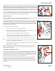
Threaded holes are provided on top of the hand grips to accept the necessary shoes or bracket to accommodate your strobes arms. Additionally, three
1/4”-20 threaded holes on the bottom of the housing can also be used for various mounting applications and a 1/4”-20 threaded hole on top of the rear half
of the housing will accept an Aquatica bracket or Base Ball that can hold a focus/video light or a extra strobe arm.
Developed with the Aquatica housing in mind, the Aquatica TLC Strobe Arm System is highly recommended for its ruggedness, precision and the quality
of its craftsmanship.
USING WIRED CONNECTORS
If using an Aquatica AD7000 Digital housing with electrical strobe connectors (supplied with either one or two
Nikonos type connectors) these will be connected to a switch board circuit that will allow you to choose between
full manual exposure or iTTL (an external converter or single housed ash is required). Optional Ikelite bulkheads
connectors are also available.
When preparing the sync cord, be sure to lubricate the O-ring on the sync cord’s connector with a light coat of the recommended O-ring lubricant for your
strobe, Also advisable is to put a light coat of O-ring lubricant on the threads of this connector.
Nikon Digital camera have a ash circuitry that will not allow two ashes to be electrically connected directly to the camera, whether in a housing or on
dry land, the wireless approach used by them prevents the triggering of the additional ashes, when two ashes or strobes are connected directly to the
camera, iTTL will stop to function and a camera freeze is likely to happen.
On your housing you will nd one (or two) bulkhead connectors, the main connector (right side) is wired through a switch board that will allow you to take
full advantage of iTTL exposure, the secondary (left side if installed) connector is always in full manual conguration and cannot be used for iTTL operation.
By default you housing is delivered with the switch board set to full manual, if the iTTL exposure is desired then it can be made in either of two methods:
1) By using a single ash from Nikon or other brand (that is iTTL compatible with your camera) in its dedicated underwater housing connected with a TTL
cord to the main connector of your Aquatica housing.
2) By using an external iTTL converter connected to the main connector of your Aquatica housing, one or two underwater strobes with TTL cords which are
then connected to this converter, (check strobe and converter manufacturer for compatibility).
Set up instruction for iTTL operation: Using the tip of a pen push all the switches to the ON (up) position, this will activate the connections on your main
bulkhead connector allowing TTL communication between the camera and the housed ash or iTTL converter.
Set up instruction for manual operation: All switches must be in the OFF (lower) position, in this case all iTTL connection are disabled and only the
ground and sync are left active, this will allow two under water strobes or housed ashes to be connected directly via the main and secondary bulkhead.
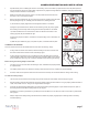
FOR OPTICAL CONNECTORS
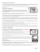
The housing with optical connectors are supplied with one dual adapter for typical straight cord used by INON and various
strobe manufacturers and two Sea & Sea angled type cords adapter, select the desired connection and install on the
optical port base, tighten the set screw into place with the supplied hexagonal wrench.
In order to use Optical triggering, the built-in ash of the camera need to be in the up position, this can be done at time
of installation or later by using the ash actuator lever (key # 23) and pressing it to release it.
If ambient light images need to be taken simply ip the ash actuator lever (key # 23) up to close the internal ash.
Note: it is advisable to turn the camera and external strobe off when travelling to your dive site in order to avoid useless drain
of the camera and strobes the batteries.
Field testing shows that mixing brands of optically triggered strobes is likely to give unreliable result and should be avoided.
Remember not to install the hot shoe if shooting optically triggered strobes (HYB version) as this hot shoe disengages the internal
built-in ash of the camera and prevent this later from working properly. Always do a few test exposures once you nished
setting up the strobes
Strobe exposure shooting tips:
Pressing the ash actuator lever down will only bring out the internal ash if no hot shoe is attached to the camera.
When used with optical connectors: this lever will release the internal ash when pressed or close it when lifted. Once the ash is up, pressing this lever
can engage the exposure compensation so you can select the corrective value with the sub command knob(key # 2) or the ash sync mode, so you can
select with the main command knob (key # 3) the desired mode (rear sync, slow sync etc.).
When using electrical connectors: This lever when pressed will engage both the exposure compensation so you can select value with the sub command
knob(key # 2) and the ash mode so you can select the mode with the main command knob (key # 3) to select the desired mode.
page 9
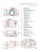
Sea & Sea Type angle
INON Type Straight cord