AquaMetrix by Water Analytics AquaMetrix 2300 Controller Installation & Operation Manual V1.3 ©Water Analytics 2014 All rights reserved.
For Your Safety Please read this entire manual before unpacking, setting up or operating this equipment. Pay attention to all danger and caution statements. Failure to do so could result in serious injury to the operator or damage to the equipment. Make sure that the protection provided by this equipment is not impaired, do not use or install this equipment in any manner other than that specified in this manual.
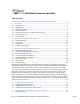
AquaMetrix by Water Analytics 2300 Multi-Parameter Controller Table of Contents AquaMetrix 2300 Controller Installation & Operation Manual ............................... 1 1. Overview ............................................................................................................................. 5 1.1. Introduction ..........................................................................................................................
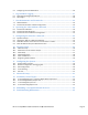
5.2. Configuring for Email Notification ...................................................................................... 26 6. Logs and Data Logging ................................................................................................. 27 6.1. Data Logging Configuration Wizard .................................................................................... 28 6.2. Alarm Logs .................................
1. Overview 1.1. Introduction The AquaMetrix 2300 Controller is a multi-input controller that is web-enabled such that it can be setup in minutes from any web browser. It contains a number of Set-up Wizards to aid the user in entering information, much of which is not reproduced in this manual. The Wizards and most other screens in the 2300 Controller are organized by a dialogue followed by a summary page with “Submit” and “Cancel” at the bottom.
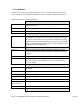
Current 0.3 A Temperature 0 to 70 0C Protection NEMA 4X, 1/4 DIN panel mount or wall mount with optional hardware Physical Mounting 1/4 DIN panel mount or wall mount with optional hardware Dimensions Front cover: 6.5” wide x 5.5” tall; rear enclosure: 3.5” wide x 3.5” tall x 4.5” deep Power 120 or 220 VAC, 60 or 50 Hz, auto-recognized. (Cable not included) Weight 2 lbs. *One expansion card slot is available 1.3.
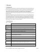
Pressing the Down arrow will cycle through all of the individual probe screens. Pressing the Enter button will bring up a Meter Action screen, allowing the user to acknowledge an alarm, if active, or setting relay trip points. Run button will bring up the Run screen once again. AquaMetrix 2300 Tank ORP Multi-Parameter Controller Tank pH 386 7.35 pH Tank D.O. 3.92 mV Tank Level ppm 88 cm Run Back Menu Enter Figure 1 - The Run display on the left reports 4 process values at a time.
These functions are geared to ensuring that the unit may be connected to a computer or the web to allow setup and configuring. When not connected to a computer or web, the unit is still operating and all non-web-based features are still fully functional. 1.5. Ethernet Connection to a network switch or router Connecting the 2300 to an existing network with the Ethernet cable allows the 2300 to be automatically assigned an IP address.
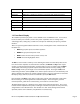
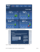
Figure 2 - Probe status screen. The screen lists all enabled sensors. Figure 3 - Config screen for setting up axes of graph shown in the Probe Status screen.
1.7. The Web Menu Clicking on one of the five top buttons brings up new screens with submenus. The overall menu structure and description for ADMIN access via the network is shown below in Table 2. Table 2 - Menu structure of the web interface Probe Status Displays the current values of the sensors along with recent history and monitor status. Config Button Allows reformatting of the history, alarm acknowledgement. Trend Chart Allows viewing of longer histories.
2. Installation and Housekeeping Mount the 2300 Controller through the front panel, with the gasket on the outside of the mounting panel. Hook the sliding mounting blocks on each side of the back of the 2300 enclosure and tighten the setscrews against the mounting panel with a torque of 4 in-lbs as shown in Figure 4. Connect an AC power cord to the power connector labeled in Figure 5. Figure 4 - Mounting hardware attached to panel with 4 in-lb of torque.
Apply power on to the 2300 Controller. The front panel will first display a splash screen with the AquaMetrix logo. If the 2300 Controller is operating properly, the LED's on the back panel indicate proper operation. The Power ON should be lit, the Fault should also be lit, and the System Operating should be blinking. The green LED on the Ethernet connector indicates a valid network link. The yellow LED will blink when there is network activity.
3. File delivery is by manual download from browser, and 4. Data is stored for configured probes only. To change these settings, go to Setup > Data Logging Configuration, and follow the Wizard. 3. Connecting and Configuring Probes 3.1. Configuring Analog Sensors In its standard configuration, the 2300 has four 4-20 mA (analog) inputs. The rear-side block connectors are shown in Figure 5 above. Wiring of a sensor depends on whether it is loop powered or externally powered; variations are shown in Figure 6.
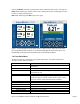
Wiring of a pulse rate sensor is shown below in Figure 7. The three wires from a typical unpowered probe are +, -, and signal. Figure 7 - Configuring a flow sensor (paddle wheel or magmeter) to one of the pulse input connections. 3.3. Probe Configuration Setup The Probe Configuration menu screen is shown in Figure 8. This screen appears in the web menu at Setup/Probe Configuration.
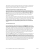
Figure 8 - Probe Configuration web page 3.4. The Probe Configuration Wizard Selecting a slot from the Probe Configuration page 1 brings up the Probe Configuration Wizard. The Probe Configuration Wizard screens contain instructions to guide you along the configuration process. The order of this process is as follows: 0. Probe definition. This step defines the probe type and its hardware input.
The probe definition page is shown in Figure 9 below. There are seven choices of probe types shown, the top three being hardware probes, the bottom four are functionally based on the outputs of other probes; we call them virtual probes (see Section 4). Set up the hardware probes first, then use these defined probes to generate any virtual probes. Monitors are set on the virtual probes just like the hardware probes. Figure 9 – New Probe Wizard containing the probe definition.
Figure 10 - Probe Configuration Wizard, page 2 Whether or not the scaling operation is a calibration depends on the signal provided by the sensor. If the sensor output comes from a transmitter then it is likely that it has already by calibrated at the transmitter. In this case the sensor signal coming into the 2300 simply needs to be scaled to translate current readings to process variable units. If the sensor is a direct sensor probe, e.g.
Figure 11 - Probe Configuration Wizard, page 3 Note that any changes to the scaling/calibration factors submitted at the end of this Wizard will reset the date of calibration for that probe. Editing other portions of the Wizard will not update the calibration date. If you are setting up the probe for the first time, we recommend that you first test the probe operation: click on Summary, review your inputs, and click on Submit.
isn’t known beforehand. A data point can also be deleted with the appropriate selection. Clear All will clear the entire graph so the mapping process can start over. A separate Data Point List is also provided which lists each data point, with one point per row. The data points can be directly changed in the Data Point List or by clicking on a plot point and moving it manually. Figure 12 - Non-linear temperature scaling example Figure 13 - Probe Configuration Wizard: Non-linear scaling.
3.7. Scale Factor The Scale Factor option just multiplies the scale factor entered by the input. This may be used to change units, or in the virtual probe configurations, to customize the output readings. 3.8. K-Factor Scaling The K-Factor option allows for a constant factor to be used to scale a frequency input into units of flow, ie volume per unit time. The K Factor is provided by the flow meter manufacturer in units of pulses per volume, where volume is typically gallons or liters.
Monitors for the other probes. The Period Counter Alarm will go off each time a multiple of the set total is reached if the Totalizer is set up with a K Factor or linear scaling. Use of the nonlinear scaling feature allows for more complex functions of this Periodic Counter Alarm. 4.2. Configuring Differential Sensors The Differential Sensor is an option for the probe type in the Probe Configuration Wizard.
5. Configuring Alarms, Relays, and Notifications Each probe can be monitored to provide multiple alarms, relay activations, and Email notifications. The 2300 is set up to allow full flexibility of assigning any or all of these outputs to any or all of the probes, including the virtual probes. You are only limited by the number of hardwired relays on your controller, four of which are standard but more may be added using an optional card.
2. Instead of green lights for the monitors on both the web probe status screen and the front panel quad screen, the monitor in alarm condition will turn red. Control-type monitors will go from green to yellow when activated. 3. Alarm events will be written into the Alarm Log, including when the alarm was activated, when acknowledged, and when returned to normal mode.
Figure 15 - Probe Configuration Wizard, page 6, Relay drop down menu Figure 16 – Probe Configuration Wizard, page 6, Select Relay. Relay 2 is selected (red shading), Relay 4 is available (yellow outline). Click inside yellow outline to select Relay 4 instead. The next step is to enter the control trip points. There are two inputs needed, the trip point to activate the relay and the trip point to reset, or deactivate the relay.
calibrated units selected for the probe. For a high alarm or control, the trip point must be greater than the reset trip point, and for a low alarm or control the trip point must be lower than the reset trip point. An error message will appear if these conditions are not met. The next input on this screen allows one to send an Email notification when the probe reading trips a condition. There are two other inputs on this page relating specifically to alarms.
5.2. Configuring for Email Notification Clicking on Next after selecting Send at Control Trip Point will bring up a new screen, page 5-A, shown in Figure 19. First select the TO Address from a drop down menu. The user may select an email address preset at Setup/Network Setup/Email Setup or choose to enter a new address. The FROM address is preset in the 2300, and may be changed at Setup > Network Setup > Email Setup > SMTP Connection Setup.
Table 3 - Email domain names for common hosts. Carrier Email Address Verizon Wireless @vtext.com AT&T @txt.att.net T-Mobile @tmomail.net Sprint @messaging.sprintpcs.com MetroPCS @mymetropcs.com Rogers Wireless @pcs.rogers.com Telus Mobility @msg.telus.com 6. Logs and Data Logging There are three types of logs that the AquaMetrix 2300 Controller generates, listed below: 1. Data Logs track scaled values for all configured Sensors and output Relays.
6.1. Data Logging Configuration Wizard Data logging will send all sensor information and all configured digital input data to a central CSV-based log file. The log files are organized using the Data Logging Configuration Wizard, located at Setup/Data Logging Configuration. Page 1 of the Wizard determines the number of days for which the 2300 keeps log file.
7. User Maintenance and Passwords 7.1. Web Passwords The 2300 Controller is password protected for web access, and PIN protected by the front panel. Users are added, changed or deleted from the Setup/User Maintenance selection menu. Each user name must be unique in the system and can contain letters or numbers. The password may only contain letters or numbers, and a PIN may be added at this point for front panel access.
Figure 21 - LCD Configuration Dialogue 8. Operating the 2300 without a Network The 2300 may be operated with or without a network connection, but web access and email notifications will not be available for the latter. However, logs will still be compiled and temporary network access will allow these to be downloaded. Once set up, the 2300 will allow front panel setting of relay trip points and calibrations, making network access not necessary for controlling and monitoring actions by the 2300.
Figure 22- Menu pages for the probe in slot 1, Tank pH, showing the first calibration page. Selecting to modify either point will bring up the screen below in Figure 23. Here you can enter the mA current and solution values that may be known for the probe, or you can do a live calibration, using the measured current for a particular solution.
Figure 24 – Calibration screens for probes with K Factor scaling. 8.2. Front Panel Relay Set Points If a relay is previously setup via the Monitor page in the Probe Configuration Wizard, the set point values for trigger and reset may be changed on the front panel. From the quad Run screen, hit the right arrow and then down arrow to arrive at the detailed screen of the probe you want to modify. Hitting Enter will bring up a menu for this probe, shown below.
Figure 26 – Change screens for relay trip and reset points. 8.3. Front Panel Save and Restore Configuration Once the 2300 has been configured with probe definitions, and email and server set ups, these settings may be saved to an external microSD card via the front panel menu. Carefully insert a microSD card in the rear slot (not the easiest insertion). Start with Menu, scroll down to Save/Restore Configuration, then select Save and Confirm. The 2300 will display a message that the save was successful.
port forwarding, also called port mapping. We recommend talking to your IT department or IT consultant to set this up. Alternatively, we have outlined some of the steps below. Every device on a LAN has an IP address that is only meaningful to users on the LAN. The router that creates the LAN has an IP address that is unique in the world. If you don’t know what that external IP is, open a browser and enter the URL: www.WhatIsMyIP.com. The website will immediately return your external IP.
solution. This will allow the wireless connection of the 2300 to a wifi-capable handheld device such as a tablet or smart phone in proximity to the 2300. Aquametrix sells a very compact, inexpensive router made by Tenda to connect the 2300 Controller to a wireless device. If you purchased a 2300 with a wireless router the router and the 2300 will already be configured and ready to go. Follow these simple instructions to connect your smart device to the 2300 through the dedicated local network. 1.
b. Default Gateway: 192.168.7.7 c. Subnet Mask: 255.255.255.0. Note that the IP address and Default Gateway are the same. That is because the computer is the gateway. On the 2300 Controller: 1. On the front panel, go to Menu>Advanced>Network Setup. 2. Select Network Type, and then Fixed (vs. DHCP.) The Fixed Network Setup screen will appear. 3. Select IP Address and use the resulting keyboard and navigation keys to enter a new IP Address. 4.
10.2. Web Server and TFTP Server Setups The second submenu is the Web Server Setup, which allows the setting of the internal web server port as well as enabling or disabling the access log and error log. If the web server port is changed, the AquaMetrix 2300 must be restarted for this change to take effect. The third submenu is the TFTP Server Setup. This configuration page allows the setting of the internal TFTP server configuration.
Figure 27 - Email configuration The second submenu is Send Test Email, which generates both an email and diagnostic message to indicate all is working or what is not. Test the SMTP connection every time there are changes made to the SMTP server settings. The third submenu is Email Message Setup. This screen allows the user to compose emails to use in the Probe Configuration menu, streamlining both the probe setup and avoiding entering duplicate data.
Monitor Name {{#relayname}} Name of the Monitor (relay or control) that was triggered Sensor Value {{#currentvalue}} Current scaled value of the Sensor at the time the email message was sent Description {{#mdescrip}} Description that was entered during the configuration of the Sensor Control State {{#relayresult}} ON or OFF state of the output relay at the time the email message was sent 10.5.
There is another user-selected option on this menu - Automatically enable all probes at startup? Clicking this box allows the 2300 Controller to come online after a power outage with all probes enabled. Without this box checked, the Controller will power up with an Enable Probe screen, requiring the user to respond to determine which if any probes are enabled. This latter option is the default, as the user must ensure that the controller relays will power up without start up problems after a power outage.
• TO Address. This is the email address used for sending the above error messages. The drop down menu lists the email addresses previously entered into the 2300, and the top menu option allows a new address to be added. 11.5. Unit List The last submenu is called Unit List, and provides a list of the probe unit values in the system. New units may be added here, or during the Probe Setup Configuration Wizard. Unwanted units may be deleted via this menu.
Table 5 - Advanced set-up parameters Menu Item Function List logged in users Provides a current listing of the users logged into the 2300. Prepare for shutdown Safely closes log files to prevent possible corruption; also available on front panel menu. Restart system Powers down system and reboots; also available on front panel menu. IO status List of current inputs with scaled outputs. Restore to factory defaults Brings up a confirmation screen to reset the 2300 to factory default settings.
13.2. 6-channel Relay Output card The 6-channel Relay Output card provides four normally open relay outputs and two relay outputs that have both normally open and normally closed contacts with the following connections: Figure 30 - 6 Relay Output Card connections 13.3. 7-channel Digital Input card The 7-channel Digital Input card provides seven additional digital inputs with the following connections: Figure 31 - Input Card connections 13.4.
Figure 32 – Analog output card connector. 14. Rebuilding a Corrupted Internal SD Card We recommend that you perform a SD card backup after the configuration has been setup and verified. The backup can be done to the same SD card that contains the version Update information. There are two things that must be done to recover from a corrupt internal SD card. First, you need to perform a rebuild operation.
Panel Mounting Dimensions MINIMUM INTERIOR CLEARENCE 4.80 15. TOP VIEW SIDE VIEW FRONT VIEW DIMENSIONS Max Panel Thickness 0.3 in 3.65 3.