
User Manual
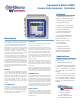

Model 2200C Conductivity Analyzer / Controller
www.WaterAnalytics.net 978-749-9949 Toll free - 855-747-7623 (855-pHProbe)
Technical Data
Related Products - Probes & Accessories
Display 4 x 7 segment 1/2” LED Display
Indicator Lights 4 LED indicators: Status, Alarm, Relay
A, Relay B
Measuring Range
Range The range is factory set but may be eld
changed
Temperature 0 to 100°C (32 to 212°F)
Power Requirements
Standard 98-132 VAC 50/60 Hz, (less than 10 VA)
Optional 196-264 VAC 50/60 Hz (less than 10 VA)
23-26 VDC (nominal current: 150 mA)
Ambient Conditions
Temperature -30 to 50°C (-22 to 122°F)
Humidity 0 to 90% RH non-condensing
Control Relays
Number Two Control Relays: Relay A, Relay B
Rating 5 A 115/230 VAC, 5A 30 VDC, SPDT
On/ Off Setpoints Field selectable full scale
Cycle Timer Field selectable 0 - 600 seconds
Manual Override AUTO/OFF/ON
Fail-safe Normal or fail safe operation
Alarm Relay
Number One High and Low Alarm Relay
Rating 5 A, 115/230 VAC, 5A 30 VDC, SPDT
Alarm High Field selectable full scale
Alarm Low Field selectable full scale
Deadband Fixed at 2% of full scale
Fail Safe Normal or fail safe operation
Relay Indicators Two individual LEDs indicate status
of two control relays and alarm relay
Analog Outputs
Non-isolated 0-1 mA, 100 ohms maximum load
Non-Isolated 0-5 VDC, 1000 ohms minimum load
Isolated 4-20 mA, 800 ohms maximum load
Output is isolated from the input, the
ground, line power and all other outputs.
Range Expand Analog outputs can be scaled to rep-
resent any segment of the instrument
scale, minimum of 10% of full scale.
Output Hold Analog outputs are placed on hold
when the instrument is in menu mode.
Temperature The 0-1 mA and 0-5 VDC outputs
can be selected to track either the pH
or the temperature of the process.
Automatic 0-100°C (32 to 212°F)
Calibration 1 point, manual
Temperature Compensation
Automatic
0-100°C (32 to 212°F) if probe has tem-
perature sensor.
Diagnostics
Invalid Entries Identied by ashing LEDs
Fail LED Illuminates red to indicate Status Fault. Scroll
to Status in Menu to determine fault code. Re-
fer to Manual for probable cause and remedy
Auto LED Illuminates red when Alarm Relay is energized,
indicating high/low process value or memory
loss.
Test Display value and analog outputs can be set to
any value for testing and diagnostic purposes
Safety & Security
Operator Password protected (activated by DIP switch)
Memory Nonvolatile memory (EPROM)
Microprocessor Watchdog timer monitors microprocessor. In-
strument automatically returns to online opera-
tion if left in menu mode for more than 10 min-
utes and no key is pressed.
Sensitivity 0.1% of span
Stability 0.1% of span per 24 hours non-cumulative
Temperature Drift Zero - 0.01% of span per °C
Span - 0.01% of span per °C
Enclosure NEMA 4X molded berglass reinforced polyes-
ter enclosure with four 1/2” conduit holes and
mounting feet for surface mount. A NEMA 4X
plug is provided for one hole.
Mounting
Standard Surface Mount
Optional Panel Mount kit P/N C35-68
Pipe Mount kit P/N C35-69
Weight 3.5 lbs. (1.6 kg)
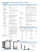
2200C Conductivity Analyzer/Controller
1 120 Vac, 50/60 Hz Power
2 240 Vac, 50/60 Hz Power
A Surface Mount
B Panel Mount
C Pipe Mount
2200C
Ordering Information
MS Cells Epoxy, low/high pressure, compression tting 3/4” NPT.
MHMSC Tank Mount Hardware for MS Cells.
MS-HTC CPVC Wet/Hot Tap Mount for MS Cells.
Conductivity Range
(µSiemens/cm)
Cell
Constant
Conductivity Range
(mSiemens/cm)
Cell
Constant
0-2 0.01 0-10 10
0-5 0.01 0-20 10
0-10 0.05 0-50 10
0-20 0.05 0-100 20
0-50 0.05 0-500 50
0-100 0.05 0-1000 50
0-200 0.5
0-500 0.5 Special Ranges
0-1000 0.5 0-15% H
2
SO
4
50
0-2000 1 0-15% NAOH 50 tt
0-5000 1