
Operating instructions
If Logic OR [3] is selected, activation of one
signal will activate the function.
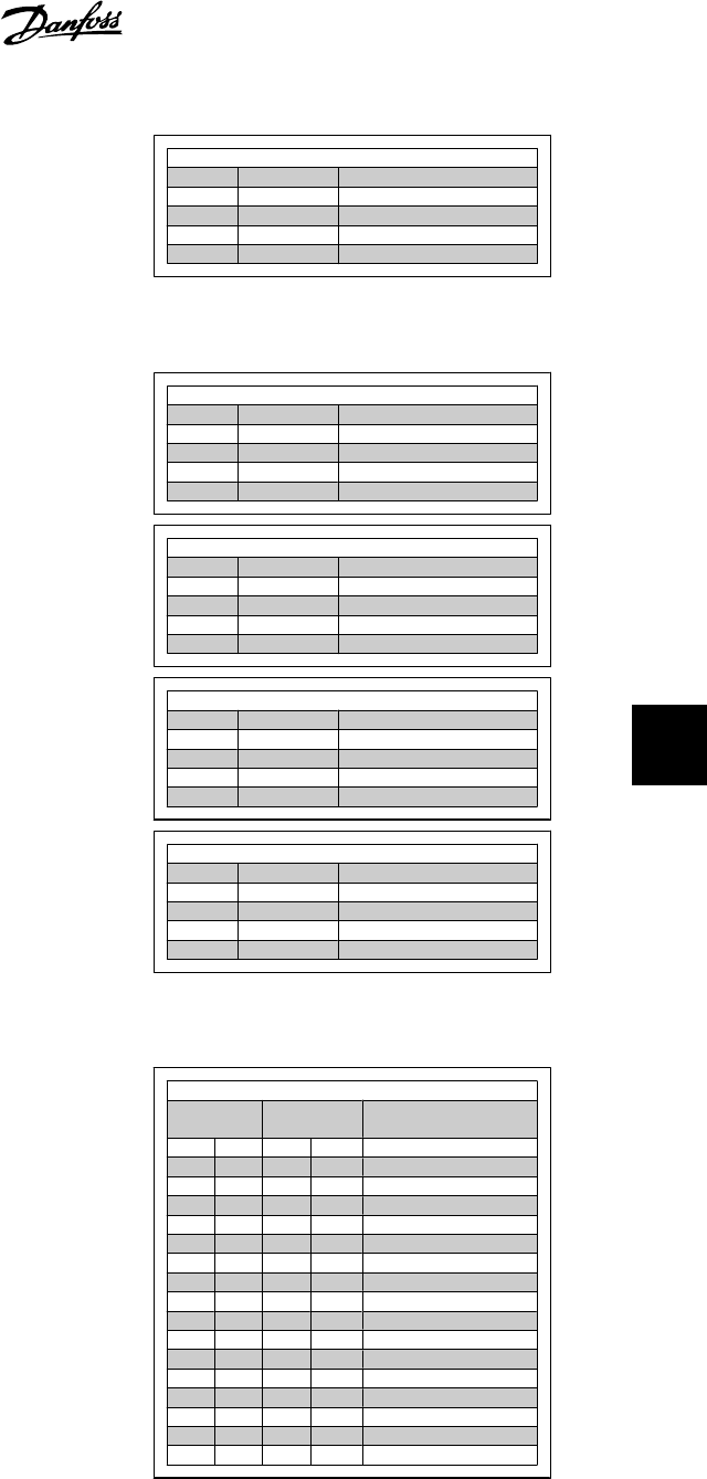
Logic OR [3]
Terminal Bit 02/03/04 Function
0 0 Coast/DC brake/Q-Stop
0 1 Coast/DC brake/Q-Stop
1 0 Coast/DC brake/Q-Stop
1 1 No Coast/DC brake/Q-Stop
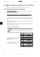
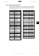
The effect of control mode upon the function of par. 8-53
Start select
and 8-54
Reversing se-
lect
:
If
Digital input
[0] is selected, the terminals
will control the start and reversing functions
Digital input [0]
Terminal Bit 06/15 Function
0 0 Stop/Anti-clockwise
0 1 Stop/Anti-clockwise
1 0 Start/Clockwise
1 1 Start/Clockwise
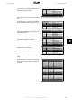
If
Serial communication
[1] is selected, com-
mands will be activated only when given via
serial communication.
Serial communication [1]
Terminal Bit 02/03/04 Function
0 0 Stop/Anti-clockwise
0 1 Start/Clockwise
1 0 Stop/Anti-clockwise
1 1 Start/Clockwise
If
Logic AND
[2] is selected, both signals must
be activated to perform the function.
Logic AND [2]
Terminal Bit 02/03/04 Function
0 0 Stop/Anti-clockwise
0 1 Stop/Anti-clockwise
1 0 Stop/Anti-clockwise
1 1 Start/Clockwise
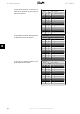
If
Logic OR
[3] is selected, activation of one
signal will activate the function.
Logic OR [3]
Terminal Bit 02/03/04 Function
0 0 Stop/Anti-clockwise
0 1 Start/Clockwise
1 0 Start/Clockwise
1 1 Start/Clockwise
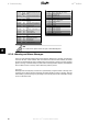
The effect of control mode upon the function of par. 8-55
Set-up select
and 8-56
Preset reference
select
:
If
Digital input
[0] is selected, the terminals
will control the set-up and preset reference
functions.
Digital input [0]
Terminal Bit 00/01,
13/14
Function
Msb Lsb Msb Lsb Preset ref., Set-up no.
0 0 0 0 1
0 0 0 1 1
0 0 1 0 1
0 0 1 1 1
0 1 0 0 2
0 1 0 1 2
0 1 1 0 2
0 1 1 1 2
1 0 0 0 3
1 0 0 1 3
1 0 1 0 3
1 0 1 1 3
1 1 0 0 4
1 1 0 1 4
1 1 1 0 4
1 1 1 1 4
VLT
®
Profibus 8. Troubleshooting
MG.33.C4.02 - VLT
®
is a registered Danfoss trademark
93
8