
Operating instructions

8. Troubleshooting
8.1. Diagnosis
PROFIBUS-DP provides a flexible means of performing diagnosis of slave units, based on diagnosis
messages.
During normal cyclical data exchange, the slave can set a diagnosis bit, which requests the master
to send a diagnosis message during the next scan cycle, instead of the normal data exchange.
The slave then answers the master with a diagnosis message consisting of standard diagnosis
information, 6 bytes, and possibly extended, vendor specific, diagnosis information. The standard
diagnosis messages covers a rather limited range of general diagnosis possibilities, whereas the
extended diagnosis function offers very detailed messaging specific to the frequency converter.
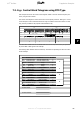
The extended diagnosis messages for the frequency converter can be found in the section
Warning
word, extended status word and alarm word
.
A master or a network analysing tool will be able to translate these diagnosis words into real text
messages using the GSD-file.
NB!
DP V1 diagnosis is supported for Profibus SW version 2 and later versions. This
means that the default setting of the Profibus option is DP V1 diagnosis. If DP V0
diagnosis is required, the setting under
DP slave Properties
must be changed.
8.2. Troubleshooting
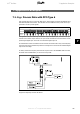
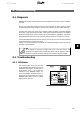
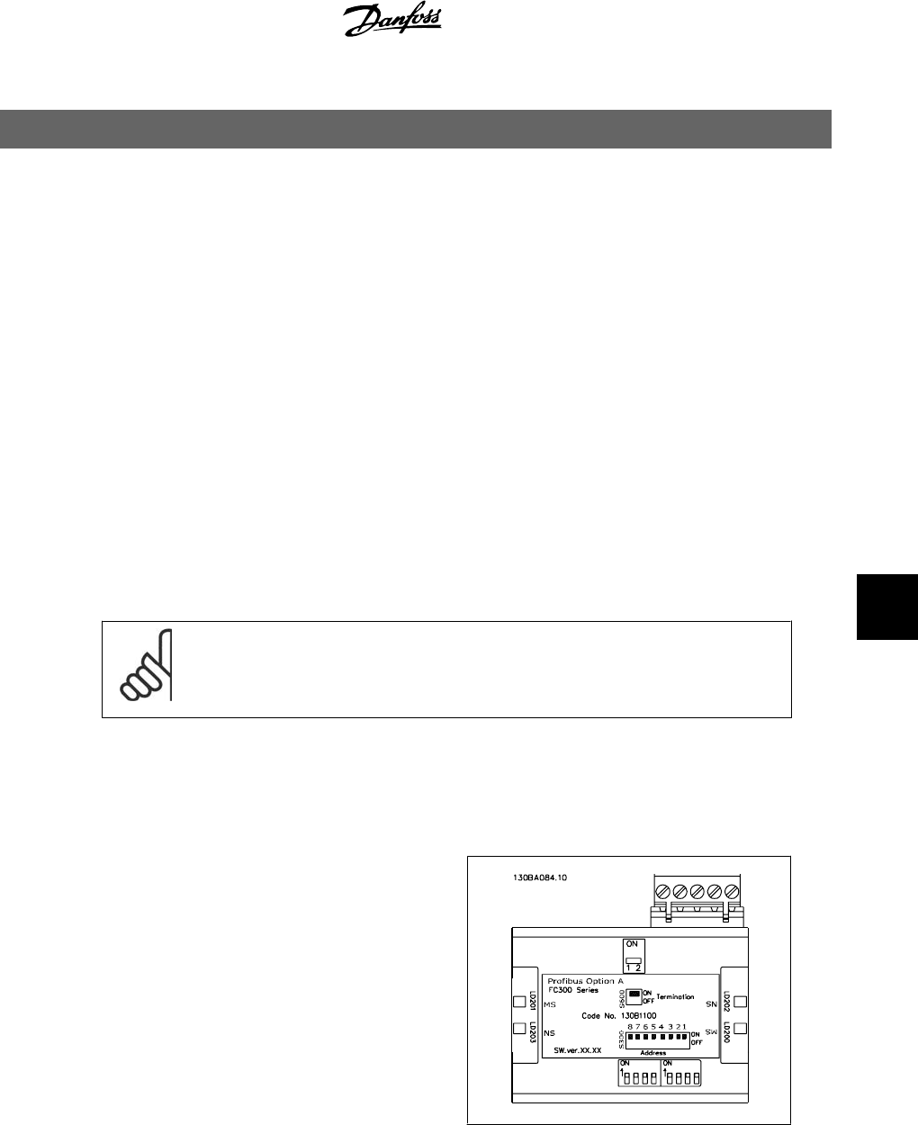
8.2.1. LED Status
First, check the LEDs. The two bi-colour LEDs
on the PROFIBUS card indicate the status of
PROFIBUS communication. The lower LED in-
dicates the Net status, i.e. the cyclical com-
munication to the PROFIBUS master. The
upper LED indicates the Module status, i.e.
acyclical DP V1 communication from either a
PROFIBUS Master Class 1 (PLC) or a Master
Class 2 (MCT10, FDT tool).
VLT
®
Profibus 8. Troubleshooting
MG.33.C4.02 - VLT
®
is a registered Danfoss trademark
89
8