
Operating instructions

34-53 Slave Index Po-
sition
34-54 Master Index
Position
34-55 Curve Position
34-56 Track Error
34-57 Synchronizing
Error
34-58 Actual Velocity
34-59 Actual Master
Velocity
34-60 Synchronizin
Status
34-61 Axis Status
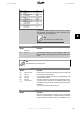
34-62 Program Status Select the parameters to be assigned to PCD 3 to 10 of the tele-
grams. The number of available PCDs depends on the telegram
type. PCDs 3 to 10 contain the actual data values of the selected
parameters. For standard Profibus telegrams, see par. 9-22.
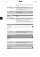
9-18 Node Address
Range: Function:
126
*
[0 - 126] Enter the station address in this parameter or alternatively in
the hardware switch. In order to adjust the station address in
par. 9-18, the hardware switch must be set to 126 or 127 (i.e.
all switches set to ‘on’). Otherwise this parameter will display
the actual setting of the switch.
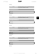
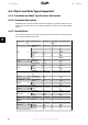
9-22 Telegram Selection
Option: Function:
Select a standard Profibus telegram configuration for the fre-
quency converter, as an alternative to using the freely configu-
rable telegrams in par. 9-15 and 9-16.
[1] Standard telegram 1
[101] PPO 1
[102] PPO 2
[103] PPO 3
[104] PPO 4
[105] PPO 5
[106] PPO 6
[107] PPO 7
[108]
*
PPO 8
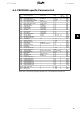
9-23 Parameters for Signals
Array [1000]
Read only
6. Parameters VLT
®
Profibus
72
MG.33.C4.02 - VLT
®
is a registered Danfoss trademark
6