
Operating instructions

4-16 Torque Limit Mo-
tor Mode
4-17 Torque Limit
Generator Mode
7-28 Minimum Feed-
back
7-29 Maximum Feed-
back
8-90 Bus Jog 1 Speed
8-91 Bus Jog 2 Speed
16-80 Fieldbus CTW 1
16-82 Fieldbus REF 1
34-01 PCD 1 Write to
MCO
34-02 PCD 2 Write to
MCO
34-03 PCD 3 Write to
MCO
34-04 PCD 4 Write to
MCO
34-05 PCD 5 Write to
MCO
34-06 PCD 6 Write to
MCO
34-07 PCD 7 Write to
MCO
34-08 PCD 8 Write to
MCO
34-09 PCD 9 Write to
MCO
34-10 PCD 10 Write to
MCO
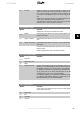
Select the parameters to be assigned to PCD 3 to 10 of the tele-
grams. The number of available PCDs depends on the telegram
type. The values in PCD 3 to 10 will then be written to the se-
lected parameters as data values. Alternatively, specify a stand-
ard Profibus telegram in par. 9-22.
9-16 PCD Read Configuration
Array [10]
None
16-00 Control Word
16-01 Reference
[Unit]
16-02 Reference %
16-03 Status Word
16-04 Main Actual
Value [Unit]
VLT
®
Profibus 6. Parameters
MG.33.C4.02 - VLT
®
is a registered Danfoss trademark
69
6