
Operating instructions


[1] Do reset Select
Do reset
[1] to return the frequency converter to the
original set-up following a control word time-out. When the val-
ue is set to
Do reset
[1], the frequency converter performs the
reset and then immediately reverts to the
Do not reset
[0] set-
ting.
Select
Do not reset
[0] to retain the set-up specified in par. 8-04,
Select setup 1-4
following a control word time-out.
This parameter is active only when
Hold set-up
[0] has been
selected in par. 8-05
End-of-Time-out Function
.
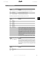
8-07 Diagnosis Trigger
Option: Function:
Enables and controls the drive diagnosis function.
[0]
*
Disable Extended diagnosis data are not sent even if they appear in the
frequency converter.
[1] Trigger on alarms Extended diagnosis data are sent when one or more alarms ap-
pear.
[2] Trigger alarms/warn. Extended diagnosis data are sent if one or more alarms/warn-
ings appear.
See section
Extended Diagnosis
for explanation of the extended
diagnosis frame.
Enabling diagnosis may cause increased bus traffic.
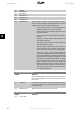
8-10 Control Word Profile
Option: Function:
[0]
*
FC profile
[1] PROFIdrive profile
[5] ODVA
[7] CANopen DSP 402 Select the interpretation of the control and status words corre-
sponding to the installed fieldbus. Only the selections valid for
the fieldbus installed in slot A will be visible in the LCP display.
For guidelines in selection of
FC profile
[0] and
PROFIdrive pro-
file
[1] please refer to the
Serial communication via RS 485
Interface
section in the
How to Programme
chapter.
For additional guidelines in the selection of
PROFIdrive profile
[1],
ODVA
[5] and
CANopen DSP 402
[7], please refer to the
Operating Instructions for the installed fieldbus.
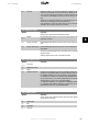
8-50 Coasting Select
Option: Function:
Select control of the coasting function via the terminals (digital
input) and/or via the bus.
[0] Digital input
[1] Bus
[2] Logic AND
[3]
*
Logic OR
VLT
®
Profibus 6. Parameters
MG.33.C4.02 - VLT
®
is a registered Danfoss trademark
65
6