
Operating instructions

The process data within the PCD part acts im-
mediately upon the frequency converter, and
can be updated from the master as quickly as
possible. The PCV part is a "handshake" pro-
cedure which means that the frequency con-
verter has to acknowledge the command,
before a new one can be written.
A positive response to the above example may
look like this:
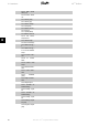
Byte Value
PCV
PCA 1 21
PCA 2 55
IND 3 00
IND 4 00
PVA 5 00
PVA 6 00
PVA 7 03
PVA 8 E8
PCD
STW 9 0F
STW 10 07
MAV 11 20
MAR 12 00
The PCD part responds according to the state and parameterisation of the frequency converter.
The PCV part responds as:
- PCA: As the request telegram, but here the RC part is taken from the response table, see the
PCA handling
section. In this example RC is 2 Hex, which is a confirmation that a parameter value
of the type long word (32 bit) has been transferred. IND is not used in this example.
- PVA: 03E8Hex in the PVA part tells that the value of par. 3-41
Ramp 1 ramp up time
is 1000,
which corresponds to 10.00.
- STW: 0F07 Hex means that the motor is running and there are no warnings or faults (for details
see the Status word table in the
Status word
section).
- MAV: 2000 Hex indicates that the output frequency is 50% of the maximum reference.
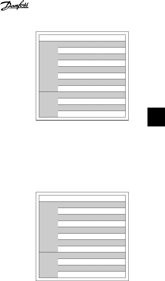
A negative response may look like this:
Byte Value
PCV
PCA 1 70
PCA 2 00
IND 3 00
IND 4 00
PVA 5 00
PVA 6 00
PVA 7 00
PVA 8 02
PCD
STW 9 0F
STW 10 07
MAV 11 20
MAR 12 00
RC is 7 Hex, which means that the request has been rejected, and the fault number can be found
in the PVA part. In this case the fault number is 2, which means that the upper or lower limit of
the parameter is exceeded. See the fault number table in the
PCA handling
section.
VLT
®
Profibus 5. How to Access the Parameters
MG.33.C4.02 - VLT
®
is a registered Danfoss trademark
61
5