
Operating instructions
5.3. PCV Parameter Access
Parameter access via the PCV channel is performed by the PROFIBUS DP V0 cyclical data ex-
change, where the PCV channel is part of the PPOs described in the chapter How to Control the
Frequency Converter.
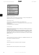
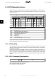
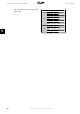
PCV PCD
1 2 3 4 5 6 7 8 9 10
PCA IND PVA CTW MRV PCD PCD PCD PCD PCD PCD PCD PCD
STW MAV
Byte
no.
1 2 3 4 5 6 7 8
9 10 11 12
13 14 15 16 17 18 19 20 21 22 23 24 25 26 27 28
Type
1:
Type
2:
Type
5:
PCV: Parameter Characteristics Value
PCD: Process Data
PCA: Parameter Characteristics (Bytes 1, 2)
IND: Sub index (Byte 3. Byte 4 is not used)
PVA: Parameter value (Bytes 5 to 8)
CTW: Control word
STW: Status word
MRV: Main reference value
MAV: Main actual value (Actual output frequency)
Using the PCV channel it is possible to read and write parameter values, as well as readout of a
number of describing attributes of each parameter.
5.3.1. PCA Handling
The PCA part of PPO types 1, 2 and 5 can handle several tasks. The master can control and
supervise parameters and request a response from the slave, whereas the slave can respond to
a request from the master.
Requests and responses
is a handshake procedure and cannot be batched, meaning that if the
master sends out a read/write request, it has to wait for the response, before it sends a new
request. The request or response data value will be limited to maximum 4 bytes, which implies
that text strings are not transferable. For further information, please see the
Application Examples
chapter
.
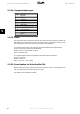
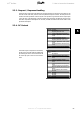
5.3.2. PCA - Parameter Characteristics
15 14 13 12 11 109876543210
RC
SMP PNU
RC: Request/response characteristics (Range 0..15)
SMP: Spontaneous Messag (Not supported)
PNU : Parameter no. (Range 1..1999)
5. How to Access the Parameters VLT
®
Profibus
56
MG.33.C4.02 - VLT
®
is a registered Danfoss trademark
5