
Operating instructions

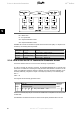
The following table shows the principle struc-
ture of the PROFIdrive Parameter Channel.
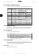
The DP V1 Parameter Request telegram con-
sists of 3 data blocks:
- a Request Header, which defines the
kind of request (Read or Write), and
the number of parameters to access.
The master sets the Request Refer-
ence, and uses this information to
evaluate the response
- an address field, where all address-
ing attributes of the desired param-
eters are defined
- a data field, where all parameter da-
ta values are placed
DP V1
Parameter re-
quest
Byte no.
Request
header
Request refer-
ence
0
Request ID 1
Axis 2
Address
field
No. of parame-
ters
3
Attribute 4
No. of ele-
ments
5
Parameter no. 6
7
Sub index 8
9
n'th parameter
no.
4+6*(n-1)
...
Data
field
Data format 4+6*n
No. of values (4+6*n)+1
Values (4+6*n)+2
n'th data value ...
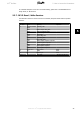
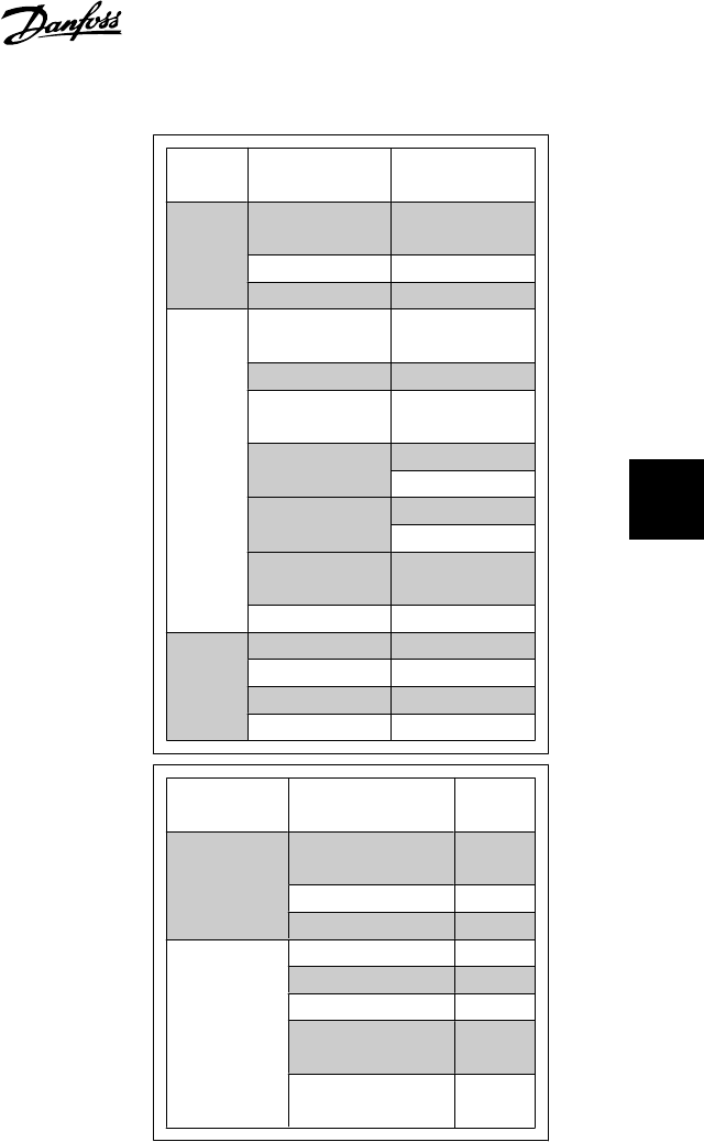
The DP V1 Parameter response telegram con-
sists of 2 data blocks:
- A response header, which indicates if
the request is performed without er-
rors (Response ID), the number of
parameters, and the Request Refer-
ence set by the master within the
corresponding request telegram
- A Data field, where the requested
data are placed. If one or more in-
ternal requests have failed, an Error
Code is placed instead of the data
values
DP V1
Parameter re-
sponse
Byte no.
Response
header
Request ref. mir-
rored
0
Response ID 1
Axis mirrored 2
Parameter
values
No. of parameters 3
Format 4
No. of values 5
Values of error
values
6
n'th parameter
value
...
As the response telegram does not include parameter addressing information, the master must
identify the structure of the response data from the request telegram.
VLT
®
Profibus 5. How to Access the Parameters
MG.33.C4.02 - VLT
®
is a registered Danfoss trademark
49
5