
Operating instructions
Bit 15, Timer OK/Timer exceeded
When bit 15 = "0", the timers for the thermal motor protection and thermal frequency converter
protection have not exceeded 100%.
When bit 15 = "1", one of the timers has exceeded 100%.
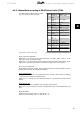
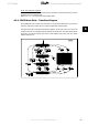
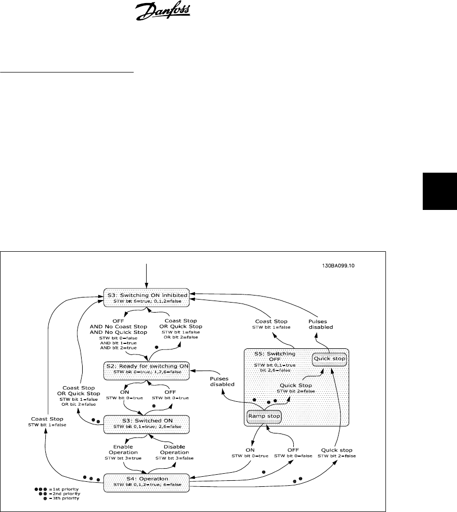
4.4.4. PROFIdrive State - Transition Diagram
In the PROFIdrive Control profile, the control bits 0 to 3 perform the basic start-up / power down
functions, whereas the control bits 4 to 15 perform application-oriented control.
The figure below shows the basic state-transition diagram, where control bits 0 to 3 control the
transitions, and the corresponding status bit indicates the actual state. The black bullets indicate
the priority of the control signals, where fewer bullets indicate lower priority, and more bullets
indicate higher priority.
VLT
®
Profibus 4. How to Control the Frequency Converter
MG.33.C4.02 - VLT
®
is a registered Danfoss trademark
35
4