
Operating instructions
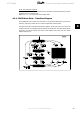
When bit 01 = "1", the frequency converter is in State 1: “Switching on inhibited”. Please refer to
the PROFIdrive State Transition Diagram, at the end of this section.
Bit 02, OFF 3/ON 3
Quick stop using the ramp time of par. 3-81
Quick stop ramp time
. When bit 02 = "0", a quick
stop and activation of the output relay 1 or 2 occurs if the output frequency is 0 Hz and if [Relay
123] has been selected in par. 5-40
Function relay
.
When bit 02 = "1", the frequency converter is in State 1: “Switching on inhibited”.
Please refer to the PROFIdrive State Transition Diagram, at the end of this section.
Bit 03, Coasting/No coasting
Coasting stop Bit 03 = "0" leads to a stop. When bit 03 = "1", the frequency converter can start
if the other start conditions are satisfied.
NB!
The selection in par. 8-50 Coasting select determines how bit 03 is linked with the
corresponding function of the digital inputs.
Bit 04, Quick stop/Ramp
Quick stop using the ramp time of par. 3-81
Quick stop ramp time
.
When bit 04 = "0", a quick stop occurs.
When bit 04 = "1", the frequency converter can start if the other start conditions are satisfied.
NB!
The selection in par. 8-51
Quick stop select
determines how bit 04 is linked with the
corresponding function of the digital inputs.
Bit 05, Hold frequency output/Use ramp
When bit 05 = "0", the current output frequency is being maintained even if the reference value
is modified.
When bit 05 = "1", the frequency converter can perform its regulating function again; operation
occurs according to the respective reference value.
Bit 06, Ramp stop/Start
Normal ramp stop using the ramp times of the actual ramp as selected. In addition, activation of
the output relay 01 or 04 if the output frequency is 0 Hz if Relay 123 has been selected in par.
5-40
Function relay
. Bit 06 = "0" leads to a stop. When bit 06 = "1", the frequency converter can
start if the other start conditions are satisfied.
NB!
The selection in par. 8-53
Start select
determines how bit 06 is linked with the cor-
responding function of the digital inputs.
Bit 07, No function/Reset
Reset after switching off.
Acknowledges event in fault buffer.
When bit 07 = "0", no reset occurs.
When there is a slope change of bit 07 to "1", a reset occurs after switching off.
VLT
®
Profibus 4. How to Control the Frequency Converter
MG.33.C4.02 - VLT
®
is a registered Danfoss trademark
31
4