
Operating instructions
4.3. Control Profile
The frequency converter can be controlled according to the PROFIdrive profile, or the Danfoss FC
profile. Select the desired control profile in par. 8-10
Control word profile
. The choice of profile
affects the control and status word only.
The
PROFIdrive control profile
and
Danfoss FC control profile
sections provide a detailed descrip-
tion of control and status data.
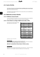
4.4. PROFIdrive Control Profile
4.4.1. PROFIdrive Control Profile
This section describes the functionality of the control word and status word in the PROFIdrive
profile. Select this profile by setting par. 8-10
Control word profile to PROFIdrive
.
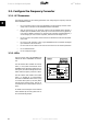
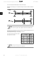
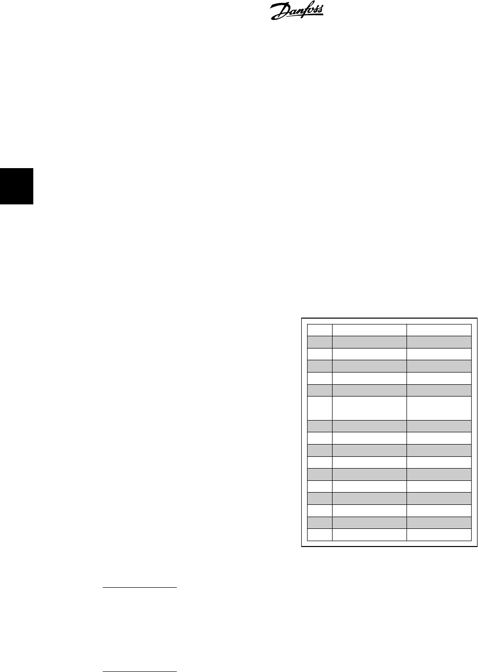
4.4.2. Control Word according to PROFIdrive Profile (CTW)
The Control word is used to send commands
from a master (e.g. a PC) to a slave.
Bit
Bit = 0 Bit = 1
00 OFF 1 ON 1
01 OFF 2 ON 2
02 OFF 3 ON 3
03 Coasting No coasting
04 Quick stop Ramp
05 Hold frequency
output
Use ramp
06 Ramp stop Start
07 No function Reset
08 Jog 1 OFF Jog 1 ON
09 Jog 2 OFF Jog 2 ON
10 Data invalid Data valid
11 No function Slow down
12 No function Catch up
13 Parameter set-up Selection lsb
14 Parameter set-up Selection msb
15 No function Reverse
Explanation of the Control Bits
Bit 00, OFF 1/ON 1
Normal ramp stop using the ramp times of the actual selected ramp.
Bit 00 = "0" leads to the stop and activation of the output relay 1 or 2 if the output frequency is
0 Hz and if [Relay 123] has been selected in par. 5-40
Function relay
.
When bit 00 = "1", the frequency converter is in State 1: “Switching on inhibited”.
Please refer to the PROFIdrive State Transition Diagram, at the end of this section.
Bit 01, OFF 2/ON 2
Coasting stop
When bit 01 = "0", a coasting stop and activation of the output relay 1 or 2 occurs if the output
frequency is 0 Hz and if [Relay 123] has been selected in par. 5-40
Function relay
.
4. How to Control the Frequency Converter VLT
®
Profibus
30
MG.33.C4.02 - VLT
®
is a registered Danfoss trademark
4