
Operating instructions
NB!
The data type for MRV and MAV is a N2 16 bit standardised value, meaning it can
express a range from -200% to +200% (8001 to 7FFF).
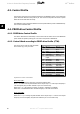
Par. 1-00
Configuration Mode
set to [0]
Speed open loop
.
Par. 3-00
Reference Range
set to [0]
Min - Max
.
Par. 3-02
Min Reference
set to 100 RPM.
Par. 3-03
Max Reference
set to 3000 RPM.
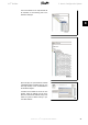
MRV / MAV
Actual
Speed
0% 0 hex 100 RPM
25% 1000 hex 825 RPM
50% 2000 hex 1550 RPM
75% 3000 hex 2275 RPM
100% 4000 hex 3000 RPM
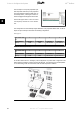
4.2.4. Process Control Operation
In process control operation par. 1-00
Configuration Mode
is set to [3]
Process
.
The reference range in par. 3-00 is alway [0]
Min - Max.
- MRV represents the process setpoint.
- MAV expresses the actual process feedback (range +/1 200%).
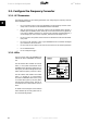
4.2.5. Influence of the Digital Input Terminals upon FC Control Mode,
Par. 8-50 to 8-56
The influence of the digital input terminals upon control of the frequency converter can be pro-
grammed in par. 8-50 to 8-56. Please note the par. 8-01
Control Site
overrules the settings in par.
8-50 to 8-56, and Terminal 37
Coasting Stop (safe)
overrules any parameter.
Each of the digital input signals can be programmed to logic AND, logic OR, or to have no relation
to the corresponding bit in the control word. In this way a specific control command i.e. stop /
coast, can be initiated by fieldbus only, fieldbus AND Digital Input, or Ether Fieldbus OR Digital
input terminal.
In order to control the frequency converter via PROFIBUS, par. 8-50
Coasting se-
lect
must be set to either Bus [1], or to Logic AND [2], and par. 8-01
Control Site
must be set to [0] or [2].
More detailed information and examples of logical relationship options are provided in the
Trou-
bleshooting chapter
.
VLT
®
Profibus 4. How to Control the Frequency Converter
MG.33.C4.02 - VLT
®
is a registered Danfoss trademark
29
4