
Operating instructions
4.2. Process Data
Use the process data part of the PPO for controlling and monitoring the frequency converter via
the PROFIBUS.
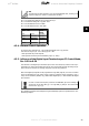
4.2.1. Process Control Data
Process data sent from the PLC to the fre-
quency converter is defined as Process Con-
trol Data (PCD).
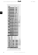
Master →
slave
1 2 3 ...... 10
CTW MRV PCD ...... PCD
PCD write
PCD 1 contains a 16-bit control word, where each bit controls a specific function of the frequency
converter, see section
Control Profile
. PCD 2 contains a 16-bit speed set point in percentage for-
mat. See section
Reference Handling
The content of PCD 3 to PCD 10 is programmed in par. 9-15
PCD write configuration
and par. 9-16
PCD read configuration
.
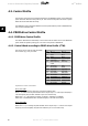
4.2.2. Process Status Data
Process data sent from the frequency con-
verter contains information about the current
state of the drive.
Slave →
master
1 2 3 ...... 10
STW MAV PCD ...... PCD
PCD read
PCD 1 contains a 16-bit status word, where each bit contains information regarding a possible
state of the frequency converter.
PCD 2 contains per default the value of the current speed of the frequency converter in percentage
format (see section
Reference Handling
). PCD 2 can be configured to contain other process sig-
nals.
The content of PCD 3 to PCD 10 is programmed in par. 9-16
PCD read configuration
.
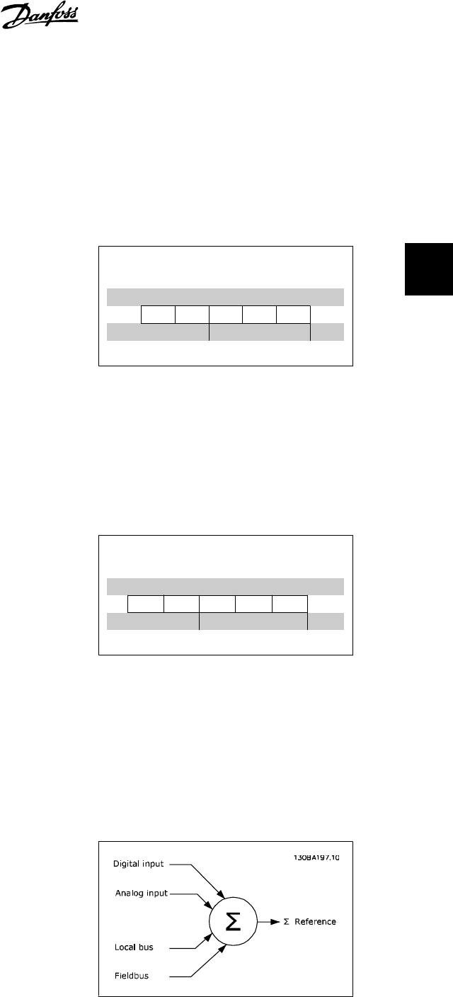
4.2.3. Reference Handling
The reference handling in FC 100, 200 and
300 is an advanced mechanism that sums up
references from different sources.
For more information on reference handling,
please refer to the relevant FC 100, 200 or 300
Design Guides.
The reference, or speed set point (MRV, send via Profibus is always transmitted to the frequency
converter in percentage format as integers represented in hexadecimal (0-4000 hex).
VLT
®
Profibus 4. How to Control the Frequency Converter
MG.33.C4.02 - VLT
®
is a registered Danfoss trademark
27
4