
Operating instructions
3.3. Configure the Frequency Converter
3.3.1. VLT Parameters
Pay particular attention to the following parameters when configuring the frequency converter
with a PROFIBUS interface.
• Par. 0-40
[Hand on] key on LCP
. If the Hand button on the frequency converter is acti-
vated, control of the drive via the PROFIBUS interface is disabled
• After an initial power up the frequency converter will automatically detect whether a
fieldbus option is installed in slot A, and set par. 8-02
Control word source
to [Option A].
If an option is added or changed in or removed from an already commissioned drive, it
will not change par. 8-02 but enter Trip Mode, and the drive will display an error
• Par. 8-10
Control word profile
. Choose between the Danfoss FC Profile and the PROFI-
drive profile
• Par. 8-50 to 8-56. Selection of how to gate PROFIBUS control commands with digital
input command of the control card
• Par. 8-03 to 8-05. The reaction in the event of a bus time out is set via these parameters
• Par. 9-18
Node address
• Par. 8-07
Diagnosis trigger
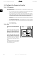
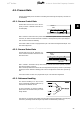
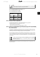
3.3.2. LEDs
The two bi-colour LEDs in the PROFIBUS card
indicate the status of PROFIBUS communica-
tion
The LED marked “NS” indicates the network
status, i.e. the cyclical communication to the
PROFIBUS master. When this light shows con-
stant green, then data exchange between the
master and the frequency converter is active.
The LED marked “MS” indicates the module
status, i.e. acyclical DP V1 communication
from either a PROFIBUS master class 1 (PLC)
or a master class 2 (MCT 10, FDT tool). When
this light shows constant green, then DP V1
communication from master classes 1 and 2 is
active.
For details of the full range of communications
status indicated by the LEDs, please refer to
the
Troubleshooting
chapter.
3. How to Configure the System VLT
®
Profibus
24
MG.33.C4.02 - VLT
®
is a registered Danfoss trademark
3