
Operating instructions
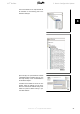
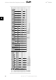
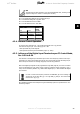
The next step is to set up the peripheral input
and output data. Data set up in the peripheral
area is transmitted cyclically via PPO types. In
the example below, a PPO type 6 Word con-
sistent is dragged and dropped to the first slot.
See the PPO types section in
How to Control
the Frequency Converter
for more informa-
tion.
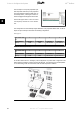
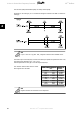
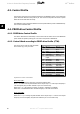
The configuration tool automatically assigns addresses in the peripheral address area. In this ex-
ample the input and output area have the following configuration:
PPO type 6:
PCD word num-
ber
1 2 3 4
Input address 256-257 258-259 260-261 262-263
Set-up STW MAV Par. 9-16.2 Par. 9-16.3
Table 3.1: PCD read (VLT to PLC)
PCD word num-
ber
1 2 3 4
Output address 256-257 258-259 260-261 262-263
Set-up CTW MRV Par. 9-15.2 Par. 9-15.3
Table 3.2: PCD write (PLC to VLT)
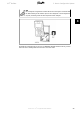
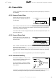
For Profibus SW version 2.x and higher, Auto-configuration of process data is supported. This
feature makes it possible to configure the process data (par. 9-15 and 9-16) from the PLC/Master.
To use Autoconfig, make sure the feature under
DP slave Properties
is enabled.
3. How to Configure the System VLT
®
Profibus
22
MG.33.C4.02 - VLT
®
is a registered Danfoss trademark
3