
Operating instructions

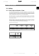
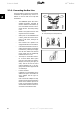

2.1.6. Connecting the Bus Line
Proper termination of the bus line is essential.
A mismatch of impedance may result in re-
flections on the line that will corrupt data
transmission.
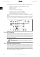
- The PROFIBUS Option Card has a
suitable termination, activated by
switch 1 located on the Profibus op-
tion. The switches must be on to ter-
minate the bus. The factory setting
is off.
- Nodes at the physical ends of each
segment must be terminated.
- When power to the PROFIBUS card
is down, please note that the termi-
nation is still active, although not
functional.
- Most masters and repeaters are
equipped with their own termination.
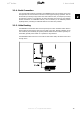
- If an external termination circuit con-
sisting of three resistors is connected
to the bus line, a 5V DC power supply
must be used. Please note that this
power supply must be galvanically
isolated from the a.c. line.
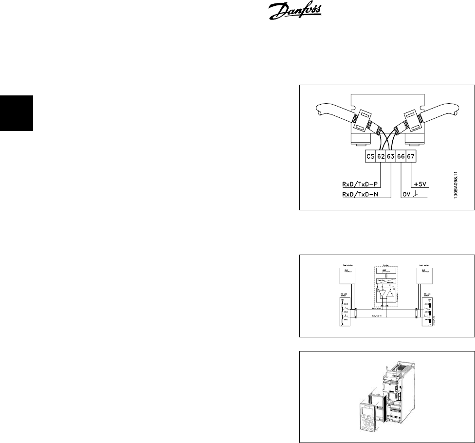
- The CS-pin on the Profibus connec-
tor is Control Select. When option
goes into active state and sends a
telegram, the CS pin goes high (+5
Volts). This can be used to control
optical transmitters etc. or for trig-
gering measurement equipment like
an oscilloscope.
- D-sub 9 connector.
If desired, a D-sub 9 adaptor can be
added as an option. The Profibus D-
sub 9 adaptor has the type no:
130B1112.
N.B.: If the D-sub 9 adaptor is used,
please be aware that the termination
switch on the Profibus option is set
to OFF, to avoid double termination.
as the Profibus D-sub 9 connector al-
so features a termination switch.
Illustration 2.1: 62 = RxD/TxD-P red cable (Sie-
mens B)
63 = RxD/TxD-N green cable (Siemens A)
2. How to Install VLT
®
Profibus
16
MG.33.C4.02 - VLT
®
is a registered Danfoss trademark
2