VLT® Profibus Contents Contents 1. Introduction 3 Safety Note 4 Technical Overview 8 Bus Topology 8 2. How to Install 13 Cabling 13 EMC Precautions 14 Connecting the Bus Line 16 3. How to Configure the System 19 Configure the PROFIBUS Network 19 Configure the Master 20 GSD File 20 Configure the Frequency Converter 24 VLT Parameters 24 LEDs 24 4.
VLT® Profibus Contents E.g.: Status Word Telegram using PPO Type 86 E.g.: PLC Programming 87 8. Troubleshooting 89 Diagnosis 89 Troubleshooting 89 LED Status 89 No Communication with the Drive 91 Warning 34 Appears even though Communication is Established 92 Drive Will Not Respond to Control Signals 92 Alarm and Warning Words 95 Fault Messages via DP Diagnosis 97 Extended Diagnosis 98 Index 2 99 MG.33.C4.
VLT® Profibus 1. Introduction 1. Introduction 1 1.1.1. Copyright, Limitation of Liability and Revision Rights This publication contains information proprietary to Danfoss A/S. By accepting and using this manual the user agrees that the information contained herein will be used solely for operating equipment from Danfoss A/S or equipment from other vendors provided that such equipment is intended for communication with Danfoss equipment over a PROFIBUS serial communication link.
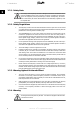
VLT® Profibus 1. Introduction 1 1.2.1. Safety Note The voltage of the frequency converter is dangerous whenever connected to mains. Incorrect installation of the motor, frequency converter or fieldbus may cause damage to the equipment, serious personal injury or death. Consequently, the instructions in this manual, as well as national and local rules and safety regulations, must be complied with. 1.2.2. Safety Regulations 1.
VLT® Profibus 1. Introduction Also make sure that other voltage inputs have been disconnected, such as external 24 V DC, load sharing (linkage of DC intermediate circuit), as well as the motor connection for kinetic back up. 1 Please refer to the relevant Operating Instructions for further safety guidelines. MG.33.C4.
VLT® Profibus 1. Introduction 1 1.3. About this Manual First time users can obtain the most essential information for quick installation and set-up in these chapters: Introduction How to Install How to Configure the System Application Examples For more detailed information including the full range of set-up options and diagnosis tools please refer to the chapters: How to Control the Frequency Converter How to Access the Parameters Parameters Troubleshooting 1.4.
VLT® Profibus 1. Introduction Features of PROFIBUS DP V1: Capital savings • 1 PROFIBUS DP V1 permits very effective use of PLC I/O capacity, in effect expanding the volume capacity of your existing PLC by up to two-thirds.
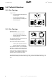
VLT® Profibus 1. Introduction 1 1.6. Technical Overview 1.6.1. Bus Topology Single master - PLC communicates with telegrams of constant length - Fits time-critical requirements - Cyclical transmission via PPO types - Extended diagnosis Illustration 1.1: PROFIBUS DP V0 1.6.2.
VLT® Profibus 1. Introduction 1.7. Assumptions 1 This manual assumes you are using a DANFOSS PROFIBUS Option Card in conjunction with a DANFOSS FC 100, 200 or 300 Series.
VLT® Profibus 1. Introduction Please also refer to www.danfoss.com/drives for frequently asked questions and additional information. 1 10 MG.33.C4.
VLT® Profibus 1. Introduction 1.11.
VLT® Profibus 2. How to Install 2 12 MG.33.C4.
VLT® Profibus 2. How to Install 2. How to Install 2 2.1. Cabling 2.1.1. Cable Lengths and Number of Codes The maximum cable length allowable in one segment is dependent on the transmission speed. The total cable length includes drop cables if any. A drop cable is the connection from the main bus cable to each node if a T-connection is used instead of permissible cable length and maximum number of nodes/frequency converters with 1, 2, 3 and 4 bus segments. Drop cable connection (i.e.
VLT® Profibus 2. How to Install The length statements in the tables above are valid for bus cable with the following properties: 2 - Impedance: 135 to 165 ohm at a measuring frequency from 3 to 20 MHz - Resistance: <110 ohm/km - Capacitance: <30 pF/m - Damping: max. 9 dB over the whole wire length - Cross section: max. 0.
VLT® Profibus 2. How to Install 2.1.4. Earth Connection It is important that all stations connected to the PROFIBUS network are connected to the same earth potential. The earth connection must have a low HF (high frequency) impedance. This can be achieved by connecting a large surface area of the cabinet to earth, for example by mounting the frequency converter on a conductive rear plate.
VLT® Profibus 2. How to Install 2.1.6. Connecting the Bus Line Proper termination of the bus line is essential. A mismatch of impedance may result in reflections on the line that will corrupt data transmission. 2 16 - The PROFIBUS Option Card has a suitable termination, activated by switch 1 located on the Profibus option. The switches must be on to terminate the bus. The factory setting is off. - Nodes at the physical ends of each segment must be terminated.
VLT® Profibus 2. How to Install 2.2. How to Install Option in Drive To install a fieldbus option in the drive you will need: - The fieldbus option - Fieldbus option adaptor frame for the FC 100, 200 and 300. This frame is deeper than the standard frame, to allow space for the fieldbus option beneath - Cable holders 2 Instructions: - Remove the LCD panel from the frequency converter - Remove the frame located beneath and discard - Push the option into place.
VLT® Profibus 3. How to Configure the System 3 18 MG.33.C4.
VLT® Profibus 3. How to Configure the System 3. How to Configure the System 3.1. Configure the PROFIBUS Network 3 All PROFIBUS stations that are connected to the same bus network must have a unique station address. The PROFIBUS address of the frequency converter can be selected via: - Hardware switches - Par. 9-18 Node address - The PROFIBUS command SSA “Set Station Address” 3.1.1.
VLT® Profibus 3. How to Configure the System Setting the PROFIBUS Address via par. 9-18 Node address: Setting the address via par. 9-18 Node address or the Profibus SSA-command is possible, if the hardware switches are set to 126 or 127 (factory switch setting). The address change will come into effect at the next power-up.
VLT® Profibus 3. How to Configure the System The FC 300 GSD file is now imported and will be accessible via the following path in the Hardware catalogue: 3 Open a Project, set up the Hardware and add a PROFIBUS Master SYSTEM. Select FC 300 then drag and drop it onto the PROFIBUS in the Hardware diagram. A window for the address of the FC 300 now appears. Select the address from the scrolldown list. Note that this address setting must match the previous address setting in par. 9-18 Node address. MG.33.
VLT® Profibus 3. How to Configure the System The next step is to set up the peripheral input and output data. Data set up in the peripheral area is transmitted cyclically via PPO types. In the example below, a PPO type 6 Word consistent is dragged and dropped to the first slot. See the PPO types section in How to Control the Frequency Converter for more informa- 3 tion. The configuration tool automatically assigns addresses in the peripheral address area.
VLT® Profibus 3. How to Configure the System NB! DP V1 diagnosis is supported for Profibus SW version 2 and higner. This means that the default setting of the Profibus option is DP V1 diagnosis. If DP V0 diagnosis is required, the setting under DP slave Properties must be changed 3 Download the configuration file to the PLC. The PROFIBUS SYSTEM should be able to go online and it will start to exchange data when the PLC is set to Run mode. MG.33.C4.
VLT® Profibus 3. How to Configure the System 3.3. Configure the Frequency Converter 3.3.1. VLT Parameters Pay particular attention to the following parameters when configuring the frequency converter with a PROFIBUS interface. 3 • Par. 0-40 [Hand on] key on LCP.
VLT® Profibus 4. How to Control the Frequency Converter 4. How to Control the Frequency Converter 4.1. PPO Types The PROFIBUS profile for frequency converters specifies a number of communication objects (Parameter Process data Objects, PPO), which are suitable for data exchange between a process controller, such as a PLC, and frequency converters. All PPOs are defined for cyclic data transfer (i.e.
PCV: PCD: PCA: IND: PVA: Type 8: Type 7: Type 6: Type 5: Type 4: Type 3: Type 2: 1 3 4 5 6 Parameter Characteristics Value Process Data Parameter Characteristics (Bytes 1, 2) Sub index (Byte 3.
VLT® Profibus 4. How to Control the Frequency Converter 4.2. Process Data Use the process data part of the PPO for controlling and monitoring the frequency converter via the PROFIBUS. 4.2.1. Process Control Data Process data sent from the PLC to the frequency converter is defined as Process Control Data (PCD). 4 Master → slave 1 2 3 ...... 10 CTW MRV PCD ......
VLT® Profibus 4. How to Control the Frequency Converter The reference (MRV) and feedback (MAV) are always scaled equally. Depending on the setting of par. 3-00 Reference Range the reference and MAV are scaled accordingly: 4 NB! If par. 3-00 is set to [0] Min - Max, a negative reference will be handled as 0%. The actual output of the frequency converter is limited by the speed limit parameters Motor Low/ High Speed Limit [RPM/Hz] in par. 4-11 to 4-14. The final speed limit is set by par.
VLT® Profibus 4. How to Control the Frequency Converter NB! The data type for MRV and MAV is a N2 16 bit standardised value, meaning it can express a range from -200% to +200% (8001 to 7FFF). Par. Par. Par. Par. 1-00 3-00 3-02 3-03 Configuration Mode set to [0] Speed open loop. Reference Range set to [0] Min - Max. Min Reference set to 100 RPM. Max Reference set to 3000 RPM.
VLT® Profibus 4. How to Control the Frequency Converter 4.3. Control Profile The frequency converter can be controlled according to the PROFIdrive profile, or the Danfoss FC profile. Select the desired control profile in par. 8-10 Control word profile. The choice of profile affects the control and status word only. 4 The PROFIdrive control profile and Danfoss FC control profile sections provide a detailed description of control and status data. 4.4. PROFIdrive Control Profile 4.4.1.
VLT® Profibus 4. How to Control the Frequency Converter When bit 01 = "1", the frequency converter is in State 1: “Switching on inhibited”. Please refer to the PROFIdrive State Transition Diagram, at the end of this section. Bit 02, OFF 3/ON 3 Quick stop using the ramp time of par. 3-81 Quick stop ramp time. When bit 02 = "0", a quick stop and activation of the output relay 1 or 2 occurs if the output frequency is 0 Hz and if [Relay 123] has been selected in par. 5-40 Function relay.
VLT® Profibus 4. How to Control the Frequency Converter Bit 08, Jog 1 OFF/ON Activation of the pre-programmed speed in par. 8-90 Bus Jog 1 speed. JOG 1 is only possible if bit 04 = "0" and bit 00 - 03 = "1". Bit 09, Jog 2 OFF/ON Activation of the pre-programmed speed in par. 8-91 Bus Jog 2 speed. JOG 2 is only possible if bit 04 = "0" and bit 00 - 03 = "1". Bit 10, Data invalid/valid Is used to tell the frequency converter whether the control word is to be used or ignored.
VLT® Profibus 4. How to Control the Frequency Converter 4.4.3. Status Word according to PROFIdrive Profile (STW) The Status word is used to notify a master (e.g. a PC) about the status of a slave.
4. How to Control the Frequency Converter VLT® Profibus Bit 05, ON 3/OFF 3 When bit 02 of the Control word is "0", then bit 05 = "0". When bit 02 of the Control word is "1", then bit 05 = "1". Bit 06, Start possible/Start not possible If PROFIdrive has been selected in par. 8-10 Control word profile, bit 06 will be "1" after a switchoff acknowledgement, after activation of OFF2 or OFF3, and after switching on the mains voltage.
VLT® Profibus 4. How to Control the Frequency Converter Bit 15, Timer OK/Timer exceeded When bit 15 = "0", the timers for the thermal motor protection and thermal frequency converter protection have not exceeded 100%. When bit 15 = "1", one of the timers has exceeded 100%. 4.4.4. PROFIdrive State - Transition Diagram In the PROFIdrive Control profile, the control bits 0 to 3 perform the basic start-up / power down functions, whereas the control bits 4 to 15 perform application-oriented control.
VLT® Profibus 4. How to Control the Frequency Converter 4.5. Danfoss FC Control Profile 4.5.1. Control Word according to FC Profile (CTW) To select FC protocol in the control word, par. 8-10 Control word profile must be set to FC protocol [0]. The control word is used to send commands from a master (PLC or PC) to a slave (frequency converter). Please refer to Application Examples for an example of a control word telegram using PPO type 3.
VLT® Profibus 4. How to Control the Frequency Converter Bit 02, DC brake Bit 02 = “0” leads to DC braking and stop. Braking current and duration are set in par. 2-01 DC Brake current and 2-02 DC Braking time. Bit 02 = “1” leads to ramping. Bit 03, Coasting Bit 03 = “0” causes the frequency converter to immediately "let go" of the motor (the output transistors are "shut off"), so that it coasts to a standstill.
VLT® Profibus 4. How to Control the Frequency Converter Bit 09, Selection of ramp 1/2 Bit 09 = "0" means that ramp 1 is active (parameters 3-40 to 3-47). Bit 09 = "1" means that ramp 2 (par. 3-50 to 3-57) is active. Bit 10, Data not valid/Data valid Is used to tell the frequency converter whether the control word is to be used or ignored. Bit 10 = "0" causes the control word to be ignored, Bit 10 = "1" causes the control word to be used.
VLT® Profibus 4. How to Control the Frequency Converter 4.5.2. Status Word according to FC Profile (STW) The status word is used to inform the master (e.g. a PC) of the operation mode of the slave (frequency converter). Please refer to Application examples for an example of a status word telegram using PPO type 3. Explanation of the Status Bits Bit 00, Control not ready/ready Bit 00 = "0" means that the frequency converter has tripped.
4. How to Control the Frequency Converter VLT® Profibus Bit 08, Speed≠ reference/speed = reference Bit 08 = "0" means that the motor is running, but that the present speed is different from the preset speed reference. It might, for example, be the case while the speed is being ramped up/ down during start/stop. Bit 08 = "1" means that the present motor present speed matches the preset speed reference.
VLT® Profibus 4. How to Control the Frequency Converter 4.6. Synchronize and Freeze The control commands SYNC/UNSYNC and FREEZE/UNFREEZE are broadcast functions. SYNC/UNSYNC is used to synchronize control commands and/or speed reference to all the connected frequency converters. FREEZE/UNFREEZE is used to freeze the status feedback in the slaves to get synchronized feedback from all connected slaves. 4 The synchronize and freeze commands affect only process data (the PCD part of the PPO). 4.6.1.
VLT® Profibus 5. How to Access the Parameters 5 42 MG.33.C4.
VLT® Profibus 5. How to Access the Parameters 5. How to Access the Parameters 5.1. Parameter Access in General In an automated SYSTEM, frequency converter parameters can be accessed either from the process controller (i.e. PLC), or from various kinds of HMI equipment. For parameter access from controllers and HMI, please observe the following: FC 100, 200 and 300 parameters are located in four separate set-ups.
VLT® Profibus 5. How to Access the Parameters 5.1.2. Read / Write in Double Word Format, DP V1 Using the special Request IDs 0X51 (read) and 0X52 (write), it is possible to read and write to all parameters containing numeric values in a general format of Double Word. The value element must be right aligned and unused MSBs filled with zeros. Example: Read of a parameter of type U8 will be transmitted as 00 00 00 xx, where xx is the value to be transmitted.
VLT® Profibus 5. How to Access the Parameters Acyclical communication takes the form of a once-off data transfer event, mainly used for Read / Write from and to parameters from process controllers, PC-based tools or monitoring SYSTEMs. 5.2.2.
VLT® Profibus 5. How to Access the Parameters 5 MC : Master Class C1...Cn: Cyclical data AC1: Acyclical data Master Class 1 AC2: Acyclical data Master Class 2 PROFIBUS DP services are activated via specific Service Access Points (SAP). For acyclical communication, the following SAP are specified: Master SAP 50 (32H) 50 (32H) 51 (33H) 51 (33H) Slave SAP 49 (31H) 0..48 (0..
VLT® Profibus 5. How to Access the Parameters For a detailed description of the DP V1 command handling, please refer to the PROFIBUS DP V1 Design Guide, ref. MG.90.EX.YY. 5.2.7. DP V1 Read / Write Services The table below shows the content of the DP V1 command / Response headers and their possible attributes. DU Byte 0 1 2 3 4..
VLT® Profibus 5. How to Access the Parameters 5.2.8. How to Use the DP V1 Acyclical Parameter Channel The PROFIdrive Parameter Channel should be used for read and write for FC 100, 200 and 300 parameters. The table below shows the structure of the PROFIdrive Parameter Channel. Using this it is possible to access the following VLT parameter values and attributes: - Parameter values of simple variable, array and visible string - Parameter description elements such as type, min./max. value, etc.
VLT® Profibus 5. How to Access the Parameters The following table shows the principle structure of the PROFIdrive Parameter Channel. The DP V1 Parameter Request telegram consists of 3 data blocks: - a Request Header, which defines the kind of request (Read or Write), and the number of parameters to access.
VLT® Profibus 5. How to Access the Parameters 5.2.9. Request / Response Attributes The table contains an overview of the possible attributes of the PROFIdrive parameter channel. Field Data type Request reference Unsigned8 Request ID Unsigned8 Response ID Unsigned8 Axis Unsigned8 Number of param- Unsigned8 eters Attribute Unsigned8 5 Number of elements Unsigned8 Parameter number Unsigned16 Subindex Unsigned16 Values 0x01..0xFF 0x01 0x02 0x42 0x51 0x52 0x01 0x02 0x81 0x82 0x00..0xFF 0x01..
VLT® Profibus 5. How to Access the Parameters 5.2.14. Number of Parameters For multi-parameter requests specifying the number of the Parameter Address and/or Parameter Value areas. For a single request the number is 1. 5.2.15. Attribute The attribute determines which kind of data to access. The frequency converter will respond to the attributes Value (10H), Description (20H) and Text (30H). 5.2.16. Attribute Value (10H) 5 The attribute value permits reading or writing of parameter values. 5.2.17.
VLT® Profibus 5. How to Access the Parameters Bit 15 14 13 12 11 10 9 8 0-7 5 Meaning Reserved Array Parameter value can be reset only Parameter has been changed from factory setting Reserved Additional text array available Parameter is read-only Standardizaton factor and variable attribute not relevant Data type Number of Array Elements Contains the number of array elements, if the parameter is an array; the string length, if the parameter value is a string; or 0 if the parameter is neither.
VLT® Profibus 5. How to Access the Parameters ID Extension Not supported PCD Reference Parameter Process data may be scaled by a parameter, e.g. the max reference of 0x4000 (in %) depends on the setting of parameter “X”. To enable the master to calculate the “real” value of the process data, it has to know the value of parameter “X”, and therefore the process data must deliver a reference to parameter “X”.
VLT® Profibus 5. How to Access the Parameters 5.2.20. Supported data types Value 3 4 5 6 7 9 10 33 35 44 54 5 Data Type Integer16 Integer32 Unsigned8 Unsigned16 Unsigned32 Visible string Octet string (byte string) N2 (standardised value) V2 (bit sequence) Error Time difference without date indication 5.2.21. Value The value field contains the parameter value of the request. When the response is negative, the field contains a corresponding error code.
VLT® Profibus 5.
VLT® Profibus 5. How to Access the Parameters 5.3. PCV Parameter Access Parameter access via the PCV channel is performed by the PROFIBUS DP V0 cyclical data exchange, where the PCV channel is part of the PPOs described in the chapter How to Control the Frequency Converter. PCV PCA Byte no.
VLT® Profibus 5. How to Access the Parameters 5.3.3. Request / Response Handling The RC portion of the PCA word defines the requests that may be issued from the master to the slave as well as what other portions of the PCV (IND and PVA) are involved. The PVA portion will transmit word-size parameter values in bytes 7 and 8, while long word size values require bytes 5 to 8 (32 bits). If the Response / Request contains array elements, the IND will carry the Array Sub-index.
VLT® Profibus 5. How to Access the Parameters Faul t no.
VLT® Profibus 5. How to Access the Parameters 5.3.5. Example This example shows how to use PPO type 1 to change the ramp-up time (parameter 3-41 Ramp 1 ramp up time) to 10 seconds and to command a start and speed reference of 50%. Frequency converter parameter settings: Par. 8-50 Coasting select: Bus Par. 8-10 Control word profile: PROFIdrive profile 5.3.6. PCV PCA – Parameter Characteristics 5 PCA part (byte 1-2). The RC part tells what the PCV part must be used for.
VLT® Profibus 5. How to Access the Parameters The whole PPO therefore has the following values in Hex: PCV PCD 5 60 PCA PCA IND IND PVA PVA PVA PVA CTW CTW MRV MVR MG.33.C4.
VLT® Profibus 5. How to Access the Parameters The process data within the PCD part acts immediately upon the frequency converter, and can be updated from the master as quickly as possible. The PCV part is a "handshake" procedure which means that the frequency converter has to acknowledge the command, before a new one can be written.
VLT® Profibus 6. Parameters 6 62 MG.33.C4.
VLT® Profibus 6. Parameters 6. Parameters 8-01 Control Site Option: Function: [0] * Digital and ctrl. word Control by using both digital input and control word. [1] Digital only Control by using digital inputs only. [2] Control word only Control by using control word only. The setting in this parameter overrides the settings in par. 8-50 to 8-56.
VLT® Profibus 6. Parameters [3] Jogging [4] Max. Speed [5] Stop and trip [7] Select set-up 1 [8] Select set-up 2 [9] Select set-up 3 [10] Select set-up 4 Select the time-out function. The time-out function activates when the control word fails to be updated within the time period specified in par. 8-03 Control Word Time-out Time. 6 - Off [0]: Resume control via serial bus (Fieldbus or standard) using the most recent control word.
VLT® Profibus 6. Parameters [1] Do reset Select Do reset [1] to return the frequency converter to the original set-up following a control word time-out. When the value is set to Do reset [1], the frequency converter performs the reset and then immediately reverts to the Do not reset [0] setting. Select Do not reset [0] to retain the set-up specified in par. 8-04, Select setup 1-4 following a control word time-out. This parameter is active only when Hold set-up [0] has been selected in par.
VLT® Profibus 6. Parameters NB! This parameter is active only when par. 8-01 Control Site is set to [0] Digital and control word. 8-51 Quick Stop Select Option: Function: [0] Digital input [1] Bus [2] Logic AND [3] * Logic OR Select control of the Quick Stop function via the terminals (digital input) and/or via the bus. NB! This parameter is active only when par. 8-01 Control Site is set to [0] Digital and control word.
VLT® Profibus 6. Parameters NB! This parameter is active only when par. 8-01 Control Site is set to [0] Digital and control word. 8-54 Reversing Select Option: Function: [0] Digital input [1] Bus [2] Logic AND [3] * Logic OR Select control of the frequency converter reverse function via the terminals (digital input) and/or via the fieldbus. Select Bus [1], to activate the Reverse command via the serial communication port or fieldbus option.
VLT® Profibus 6. Parameters [1] Bus Activates Preset Reference selection via the serial communication port or fieldbus option. [2] Logic AND Activates Preset Reference selection via the fieldbus/serial communication port, AND additionally via one of the digital inputs. [3] * Logic OR Activates the Preset Reference selection via the fieldbus/serial communication port OR via one of the digital inputs. NB! This parameter is active only when par.
VLT® Profibus 6.
VLT® Profibus 6. Parameters 16-05 Main Value [%] Actual 16-09 Custom Readout 16-10 Power [kW] 16-11 Power [hp] 16-12 Motor Voltage 16-13 Frequency 16-14 Motor Current 16-16 Torque 16-17 Speed [RPM] 16-18 Motor Thermal 16-19 KTY Sensor Temperature 6 16-21 Phase Angle 16-30 DC Link Voltage 16-32 Brake Energy / s 16-33 Brake Energy / 2 min 16-34 Heatsink Temp. 16-35 Inverter Thermal 16-38 State SL Control 16-39 Control Card Temp.
VLT® Profibus 6. Parameters 16-67 Freq. #29 [Hz] Input 16-68 Freq.
VLT® Profibus 6. Parameters 34-53 Slave Index Position 34-54 Master Index Position 34-55 Curve Position 34-56 Track Error 34-57 Synchronizing Error 34-58 Actual Velocity 34-59 Actual Master Velocity 34-60 Status Synchronizin 34-61 Axis Status 6 34-62 Program Status Select the parameters to be assigned to PCD 3 to 10 of the telegrams. The number of available PCDs depends on the telegram type. PCDs 3 to 10 contain the actual data values of the selected parameters.
VLT® Profibus 6. Parameters This parameter contains a list of signals available for selection in par. 9-15 and 9-16. 9-27 Parameter Edit Option: Function: Parameters can be edited via Profibus, the standard RS485 interface, or the LCP. [0] Disabled Disables editing via Profibus. [1] * Enabled Enables editing via Profibus.
VLT® Profibus 6.
VLT® Profibus 6. Parameters Index [0] [1] [2] [3] [4] [5] [6] [7] [8] [9] Content Manufacturer Device type Version Firmware date year Firmware date month No. of axes Vendor specific: PB Version Vendor specific: Database Version Vendor specific: AOC Version Vendor specific: MOC Version Value 128 (for Danfoss) 1 xxyy yyyy ddmm variable xxyy xxyy xxyy xxyy The device identification parameter. The data type is "Array[n] of Unsigned16“.
VLT® Profibus 6. Parameters atile memory, so changed parameter values will be retained at power-down. [0] * Off Deactivates the non-volatile storage function. [1] Store edit setup Stores all parameter values in the set-up selected in par. 9-70 in the non-volatile memory. The selection returns to Off [0] when all values have been stored. [2] Store all set-ups Stores all parameter values for all set-ups in the non-volatile memory.
VLT® Profibus 6. Parameters Read only 0* [0 - 115] This parameter displays a list of all the defined frequency converter parameters available for Profibus. 9-83 Defined Parameters (4) Array [116] No LCP access Read only 0* [0 - 115] This parameter displays a list of all the defined frequency converter parameters available for Profibus.
VLT® Profibus 6. Parameters 0* [0 - 115] This parameter displays a list of all the frequency converter parameters deviating from default setting. 9-94 Changed Parameters (5) Array [116] No LCP access Read only 0* 6 [0 - 115] This parameter displays a list of all the frequency converter parameters deviating from default setting. 16-84 Comm Option Status Word [Binary] Range: 0* Function: [0 - FFFF] Extended fieldbus comm. option status word. For more information - see section Troubleshooting.
VLT® Profibus 6. Parameters 6.3. PROFIBUS-specific Parameter List Par. No.
VLT® Profibus 6. Parameters 6.4. Object and Data Types Supported 6.4.1. Parameter and Data Type Structure Description 6.4.2. Parameter Description PROFIBUS DP has a number of describing attributes. Read/write on parameter description is performed in the PCV part using the RC commands 4/5 and the sub-index of the desired description element. 6.4.3. Size Attribute The size index and the conversion index for each parameter can be taken from the parameter list in the respective Operating Instructions.
VLT® Profibus 6. Parameters 6.4.4. Object and Data Types Supported Data types supported Short name Data type 3 4 5 6 7 9 10 33 35 54 Description Integer 16 Integer 32 Unsigned 8 Unsigned 16 Unsigned 32 Visible string Byte string Standardized value (16 bit) Bit sequence Time difference without date indication I2 I4 O2 O4 N2 V2 - 6 6.4.5. Standardized Value The frequency reference value is transmitted to the frequency converter in the form of a 16-bit word.
VLT® Profibus 7. Application Examples 7 82 MG.33.C4.
VLT® Profibus 7. Application Examples 7. Application Examples 7.1. E.g.: Process Data with PPO Type 6 This example shows how to work with PPO type 6, which consists of Control Word/Status Word and Reference/Main Actual Value. The PPO also has two additional words, which can be programmed to monitor process signals: PCV PCA Byte no.
VLT® Profibus 7. Application Examples Parameter no.
VLT® Profibus 7. Application Examples 7.2. E.g.: Control Word Telegram using PPO Type This example shows how the control word telegram relates to the PLC and the frequency converter, using FC Control Profile. The control word telegram is sent from the PLC to the frequency converter. PPO Type 3 is used in the example in order to demonstrate the full range of modules. All the values shown are arbitrary, and are provided for the purposes of demonstration only. PCV PCA PQW: 256 Bit no.
VLT® Profibus 7. Application Examples 7.3. E.g.: Status Word Telegram using PPO Type This example shows how the control word telegram relates to the PLC and the frequency converter, using FC Control Profile. The control word telegram is sent from the PLC to the frequency converter. PPO Type 3 is used in the example in order to demonstrate the full range of modules. All the values shown are arbitrary, and are provided for the purposes of demonstration only. PCV PCA PIW: 256 Bit no.
VLT® Profibus 7. Application Examples 7.4. E.g.: PLC Programming In this example PPO type 6 is placed in the following Input/Output address: Input address Set-up 256-257 258-259 Status word MAV 260-261 Motor torque 262-263 Digital input Output address Set-up 256-257 Control word 258-259 Reference 260-261 Not used 262-263 Not used 7 This network will send a start command (047C Hex) and a reference (2000 Hex) of 50% to the frequency converter.
VLT® Profibus 7. Application Examples This network reads the status on the digital inputs from the frequency converter. If digital input 18 is On it will stop the frequency converter. This network will reverse the motor when digital input 19 is ON, because par. 8-54 Reversing select is programmed to Logic AND. This network will activate the relay 02. 7 88 MG.33.C4.
VLT® Profibus 8. Troubleshooting 8. Troubleshooting 8.1. Diagnosis PROFIBUS-DP provides a flexible means of performing diagnosis of slave units, based on diagnosis messages. During normal cyclical data exchange, the slave can set a diagnosis bit, which requests the master to send a diagnosis message during the next scan cycle, instead of the normal data exchange.
VLT® Profibus 8. Troubleshooting Phases Power On Bi-colour LED Red Green Search baud rate Green Wait Parameter- Green izing Red Wait Configura- Green tion Red Data Exchange Green Red Status The PROFIBUS card is defect. Contact Danfoss Drives The PROFIBUS card is OK. Searching for the baud rate. Check the connection to the master if it stays in this state. Baud rate found - waiting for parameters from the master. Wrong parameters from the master.
VLT® Profibus 8. Troubleshooting 8.2.2. No Communication with the Drive If there is no communication with the drive, proceed with the following checks: Check 1: Is the cabling correct? Check that the red and green cables are connected to the correct terminals as shown in the diagram below. If the cables are crossed, no communication is possible. 62 = RxD/TxD-P red cable 63 = RxD/TxD-N green cable Check 2: Is the correct GSD file installed? Download the correct GSD file from http://danfoss.com/drives.
VLT® Profibus 8. Troubleshooting 8.2.3. Warning 34 Appears even though Communication is Established If the PLC is in stop mode Warning 34 will appear. Check that the PLC is in run mode. 8.2.4. Drive Will Not Respond to Control Signals Check 1: Is the Control word valid? If bit 10=0 in the Control word, then the drive will not accept the Control word, because the default setting is bit 10=1. Set bit 10=1 via the PLC.
VLT® Profibus 8. Troubleshooting If Logic OR [3] is selected, activation of one signal will activate the function. Logic OR Terminal 0 0 1 1 [3] Bit 02/03/04 Function 0 Coast/DC brake/Q-Stop 1 Coast/DC brake/Q-Stop 0 Coast/DC brake/Q-Stop 1 No Coast/DC brake/Q-Stop The effect of control mode upon the function of par.
VLT® Profibus 8. Troubleshooting If Serial communication [1] is selected, commands will be activated only when given via serial communication. If Logic AND [2] is selected, both signals must be activated to perform the function. Serial communication [1] Terminal Msb 0 0 0 0 0 0 0 0 1 1 1 1 1 1 1 1 If Logic OR [3] is selected, activation of one signal will activate the function.
VLT® Profibus 8. Troubleshooting 8.2.5. Alarm and Warning Words Alarm word, Warning word and PROFIBUS warning word are shown on the display in Hex format. If there is more than one warning or alarm, a sum of all warnings or alarms will be shown. Alarm word, warning word and PROFIBUS warning word can also be displayed using the serial bus in par. 16-90, 16-92 and 9-53.
VLT® Profibus 8. Troubleshooting Bit (Hex) 00000001 00000002 00000004 00000008 00000010 00000020 00000040 00000080 00000100 00000200 00000400 00000800 00001000 00002000 00004000 00008000 FC 100, 200 and 300 Unit di- PROFIBUS warning word (Par.
VLT® Profibus 8. Troubleshooting Alarms Following an alarm message the frequency converter will enter Fault condition. Only after the fault has been alleviated and the master has acknowledged the alarm message by setting bit 7 in the control word, can the frequency converter resume operation. Alarms within the frequency converter are represented by a single bit within an alarm word. An alarm word is always an action parameter. Bit status FALSE [0] means no fault, while bit status TRUE [1] means fault. 8.
VLT® Profibus 8. Troubleshooting 8.2.8. Extended Diagnosis Using the extended diagnosis function, alarm and warning information can be received from the frequency converter. The setting of par. 8-07 Diagnosis trigger determines which frequency converter events should trigger the extended diagnosis function. When par. 8-07 Diagnosis trigger is set to Disable [0], no extended diagnosis data are sent regardless of whether they appear in the frequency converter. When par.
VLT® Profibus Index Index A Abbreviations 11 Alarm Word 95 Alarm Word, 16-90 78 Axis 50 B Bus Jog 2 Speed 68 Bus Topology 8 C Cable Lengths And Number Of Codes 13 Cable Routing 15 Coasting Select, 8-50 65 Complete Description 53 Connecting The Bus Line 16 Connection Of The Cable Screen 14 Control Profile 30 Control Site, 8-01 63 Control Word According To Fc Profile (ctw) 36 Control Word According To Profidrive Profile (ctw) 30 Control Word Timeout Function 63 D Data Excha
VLT® Profibus Index M Master Class 1 Connection 45 Master Class 2 Connection 45 Mct 10 Pc Software Tool 6 Mrv 59 N Name 52 No Communication With The Drive 91 Number Of Array Elements 52 Number Of Parameters 51 P Parameter Access 43 Pca - Parameter Characteristics 56 Pca Handling 56 Pcd 59 Pcd Reference Parameter 53 Pcv 59 Pcv Parameter Access 56 Ppo Types 25 Preset Reference Select, 8-56 67 Process Control Data 27 Process Control Operation 29 Process Control, 9-28 73
VLT® Profibus Index W Warning 34 92 Warning Word 95 Warning Word, 16-92 78 MG.33.C4.