
Operating instructions

IMPORTANT NOTE
IMPORTANT NOTE
Read Section 4, PLUMBING SYSTEM CLEANUP, for instructions on some procedures that MAY need to be performed prior to
installation.
Step 1
Shut off all water at main supply. On a PRIVATE WELL SYSTEM, turn off power to pump and drain pressure tank. Make certain pres-
sure is relieved from complete system by opening nearest faucet to drain system.
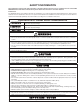
CAUTION
CAUTION
To reduce the risk associated with property damage due to water leakage:
• When water supply is shut off, shut off fuel or electric power to water heater.
Step 2
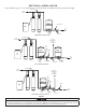
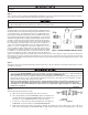
Cut main supply line as required to fi t Hydro-Charger in plumbing between
well pump and pressure tank (Hydro-Charger may be installed in a vertical
or horizontal position). The Hydro-Charger has been supplied with both 1”
threaded and 1” barbed (insert) fi ttings to allow for installation with various
types of piping materials. When using the threaded nipples, use thread tape
only. When using barbed (insert) fi ttings, appropriate pipe clamps must be
used. Once installed, the quick release nipples allow the Hydro-Charger to
be rotated, so the air draw adjustment screw is accessible for adjustment
by a small bladed screwdriver. Allow at least 10 inches of straight run of
1” pipe on both INLET and OUTLET side of the Hydro-Charger. Refer to
Figure 2 for correct assembly. The quick release nipples also acts as a
union to facilitate the Hydro-Charger removal, inspection and cleaning as
needed. With an installation on PVC pipe and copper tubing it may require
the addition of a normal plumbing union to aid in removal from the plumb-
ing due to the rigidity of that type of material. Make certain the directional
arrows on the Hydro-Charger points toward the pressure tank and the pressure control switch is located on the pressure tank side of
Hydro-Charger as in Figure 1. Rapid cycling of pump may occur if the pressure control switch is located on well side. If a check valve
is located between Hydro-Charger and pressure tank, it may prevent the Hydro-Charger from performing properly. Relocate to well
side of Hydro-Charger.
Step 3
Turn back on the power to the well pump and pressurize the water lines to allow for adjustment of the Hydro-Charger. Check for leaks
and adjust as necessary.
IMPORTANT NOTES
IMPORTANT NOTES
• Do not apply heat near Hydro-Charger, as damage may occur. On badly scaled, older plumbing systems, it may be advanta-
geous to install a WYE STRAINER to help prevent plugging of the Hydro-Charger nozzle with scale or debris. The use of a
WYE STRAINER must precede the Hydro-charger on the inlet side by a MINIMUM OF 10”.
• If existing water system includes a captive-air type pressure tank (bladder) and it is desirable to install an additional air to water
type with an air release (not as a split steam type installation) install an air to water type pressure tank between the Hydro-
Charger and the existing captive air type pressure tank.
• Before proceeding with Hydro-Charger installed, re-verify adequate pumping rate pumping by following the proce-
dure described in SECTION 2. After verifi cation of adequate fl ow, depressurize system as described previously.
• If installation is to be split streamed prior to fi lter vessel or is a public water supply see Figure 1, or refer to Special
Instructions on page 3-6.
Step 4
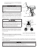
Set Hydro-Charger by following these steps:
a) Open nearest faucet until well pump starts, then close faucet.
b) Place a fi nger lightly over the SUCTION PORT (Figure 3). A slight suction
should be detected for approximately ONE THIRD (1/3) of pumping cycle
time. (Do not confuse with ONE THIRD (1/3) of pressure range).
c) If suction is too short, increase by turning air adjustment screw (Figure 3),
CLOCKWISE. To decrease duration, turn COUNTERCLOCKWISE.
d) Repeat steps (a) through (c) until proper setting is obtained. The optimum cycle time is 60 seconds or more, with an air
draw of 20 seconds minimum. Position DRAIN LINE over drain and secure fi rmly. To prevent back-siphoning of sewer water,
3-2
Figure 2: HYDRO-CHARGER INSTALLATION
Figure 3