
Operating instructions

Periodic media replenishment will be required if your raw water has a pH below 7 and/or a manganese content over 0.2 ppm. The
frequency of replenishment will depend on raw water pH; hardness; iron; manganese; amount of water used; and the size of the fi lter
selected.
Should your raw water have a low pH, it is recommended that you check the media level every 6-12 months. To check the level follow
these steps:
1) Place light behind mineral tank and observe media level. If media is down 2-3 inches below line on side of tank, add pH Booster
through fi ll port adapter. Relieve pressure before removing fi IIport cap. Manually backwash fi lter to mix pH Booster into media
bed.
If you are unable to see through tank with light proceed to #2.
2) Turn BYPASS VALVE to “BYPASS” position.
3) Manually stage fi lter into “BACKWASH” to relieve water pressure.
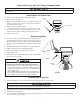
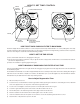
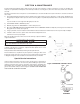
4) Disconnect CONTROL VALVE from BYPASS VALVE. Remove CONTROL VALVE from fi llport by removing latch and disassem-
bling quick release clamp. (See Figure 9)
5) Using a yard stick, measure media level. Remember media should be down 19-20 inches from the top of the fi IIport adapter.
6) If media is down 2-3 inches, siphon water from tank and add pH Booster to
return the level to the proper depth.
When the media level is below 19 inches from the tank top, replenish it with the
original media blend.
IMPORTANT NOTE
IMPORTANT NOTE
When adding pH Booster or Media through top of fi llport adapter, be sure to
cover center distributor tube with plastic cap or tape.
Over time it is best to schedule maintenance frequently enough so only a couple
of bottles of pH Booster is required to replenish the fi lter. pH Booster is sold in
3.5 pound bottles by your dealer.
Always backwash fi lter immediately following media replenishment.
Another maintenance step which may be required is resetting the timer to the
proper time of day. It may be in error due to power outages and/or changes due
to daylight savings time. This should be checked at least every six months.
Special Service Instructions:
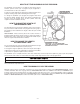
Under normal circumstances removal of valve should never be required. How-
ever, if it must be removed, it can be done by disassembling the quick release
clamp, by removing latch. Pressure should be relieved before attempting any
disassembly. Upon reassembly, all O-rings should be lubricated with silicone
grease. Reassemble clamp as shown in Figure 10. MAKE SURE ARROWS ON
LATCH SIDE OF CLAMP ARE ALIGNED.
6-1
SECTION 6: MAINTENANCE
Figure 10.
CLAMP
ASSEMBLY
Figure 9. REMOVING CONTROL VALVE