
Operating instructions

3-6
SPECIAL INSTRUCTIONS FOR SPLIT-STREAM AND
PUBLIC WATER SUPPLY TYPE INSTALLATIONS:
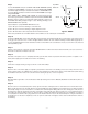
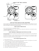
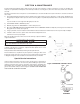
For SPLIT-STREAM type installations, a secondary PRESSURE TANK must be installed as in Figure 1. On PUBLIC WATER SUPPLY
type installations, a PRESSURE TANK must be installed as in Figure 1.
The pressure tank should be of same capacity as would normally be installed if water system were a standard private well type. Also
note both applications require a NORMALLY-CLOSED SOLENOID VALVE. Follow standard installation procedures above with follow-
ing additions and modifi cations.
1) Install PRESSURE TANK (See Figure 1) or SECONDARY PRESSURE TANK (See Figure 1) as indicated by appropriate
diagram.
2) Install NORMALLY-CLOSED SOLENOID VALVE, 110/120V, 60Hz after water meter on public water supply installations or
AFTER a line split for untreated water on split stream installations.
3) On both types installation, install HYRDO-CHARGER between PRESSURE TANK (SECONDARY PRESSURE TANK on SPLIT-
STREAM type installation) and NORMALLY-CLOSED SOLENOID VALVE.
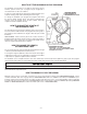
4) Install PRESSURE SWITCH after HYDRO-CHARGER and wire it to SOLENOID VALVE (SECONDARY PRESSURE SWITCH
on SPLIT-STREAM). Set HIGH pressure on PRESSURE SWITCH (which controls opening and closing of SOLENOID VALVE) 2
to 3 psi LOWER than LOW pressure on PRIMARY PRESSURE SWITCH. EXAMPLE: If PRIMARY PRESSURE SWITCH is set
at 40/60 psi, set SECONDARY PRESSURE SWITCH 20/38 psi.
For PUBLIC WATER SUPPLY type installations, contact your local water department or plant operator and ask what the normal LOW
system pressure is. Set HIGH pressure on PRESSURE SWITCH 2 to 3 psi LOWER than this fi gure.
IMPORTANT NOTE
IMPORTANT NOTE
Failure to set PRESSURE SWITCH as described above will NOT allow proper closing of SOLENOID VALVE
during periods of low system pressure. Improper function of SOLENOID VALVE will cause total failure of system.