
Operating instructions

Step 9
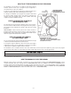
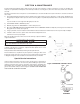
Loosen SET-SCREW and pull out DRAIN LINE FLOW CONTROL (DLFC)
assembly from VALVE BODY (see Figure 5). Unscrew DRAIN LINE ELBOW
from DLFC. Apply PTFE tape to threads. Reassemble to VALVE BODY, mak-
ing certain DLFC assembly is FULLY inserted into VALVE BODY before tight-
ening SET-SCREW.
Attach DRAIN LINE to DRAIN LINE FITTING. To prevent back pressure
from reducing fl ow rate below minimum required for backwash, DRAIN LINE
MUST be sized according to run length and relative height. Be careful not to
bend fl exible drain tubing sharply enough to cause “kinking” (if kinking occurs
DRAIN LINE MUST be replaced!).
Typical examples of proper DRAIN LINE diameters are:
1 )1/2 in. ID up to 15 ft. when discharge is lower than inlet.
2) 5/8 in. ID up to 15 ft. when discharge is slightly higher than inlet.
3) 3/4 in. ID when drain is 25 ft. away and/or drain is installed overhead.
Some areas prohibit the use of fl exible drain lines. Check with local code offi cials prior to installation.
Step 10
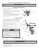
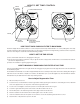
Position the DRAIN LINE over the waste drain pipe and secure fi rmly. To prevent back siphoning of sewer water or grey water, provide
an air gap of at least two inches or 2 times the pipe diameters between the end of drain line tubing and waste drain (Figure 6). Do
not raise the DRAIN LINE more than 10 feet above the fl oor. Check with local code offi cials to ensure you conform to local, state and
national plumbing codes.
Step 11
Plug the control valve into a properly grounded 110/120V 60 Hz non switched electrical outlet. Check with your local code enforce-
ment offi ce to determine if it meets local codes.
Step 12
Turn back on the power source to well pump and slowly open the shut off valve to pressurize the water system. If on a public or com-
munity water supply open the main shut off valve to the dwelling.
Step 13
Set the time of day by referring to Page 5-3 “How to set the Time-of-Day”.
Step 14
Open the valve on the water supply as required to pressurize the water lines to the dwelling or fuel source. The power to the water
heater or boiler needs to be established once water has been allowed to fl ow back into the device, if it was drained at any time during
the installation. Check for leaks on all connections before leaving the job site, correct as required.
Step 15
Manually initiate regeneration of the Iron Reduction Filter by referring to the “How To Manually Backwash Your Filter At Any Time” on
page 5-3.
Step 16
Once the valve is in the backwash position slowly open the inlet side of the bypass valve to allow water to fl ow into the fi lter vessel.
Water should start to fl ow into the drain. Allow for any air that might have been trapped to leave the fi lter and go to drain. This will be
detected by changes in noise in the drain line or is visible in the semi-transparent tubing. Once the air is entirely gone slowly increase
the water fl ow to drain by opening the inlet side of the bypass valve until fully open. Refer to Figure 5 for correct positioning. At the
end of fi lling, the water should be clear. If not, allow the valve to complete the manual regeneration process and initiate once again. It
is very important to allow the unit to purge all fi nes from the media in the fi lter vessel to the waste drain prior to using the water. Once
the fl ushing process has been completed you now can open the outlet side of the bypass valve to allow for fi ltered water to fl ow into
the dwelling.
EQUIPMENT
DRAIN LINE
DRAIN
2" REF.
AIR GAP
Figure 6. DRAIN
3-4