
Operating instructions
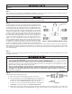

provide an air gap of at least 2 inches or 2 pipe diameters between
end of drain hose and drain (Figure 6). Do not raise DRAIN LINE
more than 10 ft. above fl oor.
IMPORTANT NOTE
IMPORTANT NOTE
When the duration of the suction is too long, the cold water may have a
milky appearance caused by excess air in the water system. Correct this
condition by reducing the duration of suction. This condition is commonly
associated with bladder type pressure tanks. In extreme cases where
elimination of excess air prevents system from performing satisfactorily,
it may be necessary to install an air to water pressure tank with an air
release valve.
Step 5
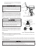
If media is already in the MEDIA TANK proceed to Step 6. If media is shipped
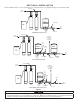
separately, add media through fi llport adapter using funnel (Figure 4). Fillport
cap can be removed by removing the quick release clip. NEVER ADD MEDIA
ABOVE LINE INDICATED ON SIDE OF TANK. You may have received more
media than required for the initial fi ll, save extra media for future replenish-
ment.
Reinstall fi llport cap. Make sure cap is fully inserted before reinstalling clip.
CAUTION
CAUTION
To reduce the risk associated with skin, eye, and respiratory tract ir-
ritation from dust from fi lter media during installation:
• Gravel and several types of fi lter media may be used in this product,
depending upon the application. During installation, dust may cause
irritation to skin, eyes, and respiratory tract, and may affect lungs.
• Utilize a NIOSH-approved dust fi lter mask and appropriate eye protec-
tion when handling and pouring gravel and fi lter media.
• Refer to MSDS documents for further safety information.
Step 6
Turn off the electrical source to the water well pump or the close the water
shut off valve on a municipal water supply to the dwelling once again. De-
pressurize the water system by opening the nearest faucet to drain water
from the water system in order to allow the installation of the Chem-Free
Iron Reduction System.
Step 7
Determine location and cut the water line on the supply side of the pressure
tank as required to fi t the plumbing to the control valve connection fi ttings.
You may want to install a separate three valve bypass prior to the control valve in case the supplied bypass valve requires mainte-
nance in order to provide undisturbed water use.
Step 8
Assemble and attach bypass valve to the control valve. See Figure 5 if needed. Make certain the water enters inlet and discharges
through the outlet side of the bypass valve. Arrows can be viewed on the bypass valve to confi rm the correct fl ow path. At this time
make certain the bypass valve is in the bypass position and leave in that position until instructed to place in the service position. Refer
to Figure 5 for proper operation.
CAUTION
CAUTION
To reduce the risk associated with property damage due to water leakage:
• Do not use torches or other heat sources near plastic plumbing, as damage may occur.
• Take care when using pliers or pipe wrenches to tighten plastic fi ttings, as damage may occur.
• On plastic fi ttings, use thread sealing tape only. Never use pipe sealant or pipe dope on plastic fi ttings, as damage may occur.
3-3
Figure 5 . INLET/OUTLET CONNECTIONS
BYPASS
BYPASS
BYPASS VALVE
CLIP & SCREW
FLAT CAP
SERVICE
YOKE
CONTROL VALVE BODY
FILL PORT
ADAPTER
OUT
IN
SET SCREW
BYPASS
DRAIN LINE
ELBOW
FLOW CONTROL ASSEMBLY
ROTATE
KNOBS
FILLPORT
BODY
FUNNEL
Figure 4. FILLING MEDIA TANK