INSTALLATION AND OPERATING INSTRUCTIONS CHEM-FREE IRON REDUCTION SYSTEMS MODELS: MCA0750 MCA1000 MCA1500 MCA2000 MCA0751 MCA1001 MCA1501 MCA2001 MCA3001 APIR075S APIR100S APIR200S APIR075M APIR100M APIR200M MCA0750M MCA1000M MCA1500M MCA2000M MCA0751M MCA1001M MCA1501M MCA2001M MCA3001M Installer, please leave with homeowner. a 3M company CUNO Incorporated 400 Research Parkway Meriden, CT 06450 U.S.A. www.cuno.com Manufactured and sold under U.S.
SAFETY INFORMATION Read, understand, and follow all safety information contained in these instructions prior to installation and use of the CUNO MCA/APIR Series Chem-Free Iron Reduction Systems. Retain these instructions for future reference. Intended use: The CUNO Chem-Free Iron Reduction Systems are intended for use in reducing dissolved and precipitated iron in water in homes and have not been evaluated for other uses.
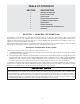
TABLE OF CONTENTS SECTION DESCRIPTION 1 GENERAL INFORMATION 2 BEFORE INSTALLATION 3 INSTALLATION 4 BACKWASHING INSTRUCTIONS 5 PLUMBING SYSTEM CLEAN-UP 6 MAINTENANCE 7 TROUBLESHOOTING 8 SPECIFICATIONS AND OPERATING DATA 9 WARRANTY SECTION 1: GENERAL INFORMATION Congratulations on your purchase of a Chem-Free Iron Reduction System! The Chem-Free System reduces dissolved, precipitated and bacterial iron from your water supply.
SECTION 2: BEFORE INSTALLATION Inspecting And Handling Your Iron Reduction Filter: Inspect the equipment for shipping damage. If damaged, notify the transportation company and request a damage inspection. Handle the filter unit with care. Damage can result if dropped or if set on sharp, uneven projections on the floor. Do not turn the filter unit upside down.
generally recommended (but only if the pumping rate is sufficient to backwash the larger size). If, however, the manganese concentration is low (0.1 ppm or less) and the pH is 6.5 or higher, a Chem-Free Iron Reduction filter containing standard Chem-Free filter media will generally perform satisfactorily, although backwashing should be performed at more frequent intervals.
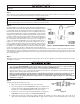
Check Your Water Pressure And Pumping Rate: Two water system conditions must be checked carefully to avoid unsatisfactory operation or equipment damage: 1) MINIMUM water pressure required at the filter tank inlet is 20 psi and MAXIMUM water pressure is 100 psi. If you have a private well, the gauge on the pressure tank will indicate the high and low system pressure.
IMPORTANT NOTES A properly sized pressure tank of either style will require a minimum pump cycle of 60 seconds to refill from the well pump on-to-off pressure settings. If cycle time of pump is less than 60 seconds, pressure tank is too small, causing excessive wear on the pump and probable failure of the filter system.
SECTION 3: INSTALLATION Proper installation sequence of iron reduction filter is very important. Refer to the diagram following for your particular supply. FILTERED WATER FILTERED SOFT WATER PRESSURE HYDRO-CHARGER TANK BRINE MAKER RAW WELL WATER SOFTENER IRON REDUCTION FILTER PRESSURE SWITCH.
IMPORTANT NOTE Read Section 4, PLUMBING SYSTEM CLEANUP, for instructions on some procedures that MAY need to be performed prior to installation. Step 1 Shut off all water at main supply. On a PRIVATE WELL SYSTEM, turn off power to pump and drain pressure tank. Make certain pressure is relieved from complete system by opening nearest faucet to drain system.
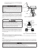
provide an air gap of at least 2 inches or 2 pipe diameters between end of drain hose and drain (Figure 6). Do not raise DRAIN LINE more than 10 ft. above floor. IMPORTANT NOTE When the duration of the suction is too long, the cold water may have a milky appearance caused by excess air in the water system. Correct this condition by reducing the duration of suction. This condition is commonly associated with bladder type pressure tanks.
Step 9 Loosen SET-SCREW and pull out DRAIN LINE FLOW CONTROL (DLFC) assembly from VALVE BODY (see Figure 5). Unscrew DRAIN LINE ELBOW from DLFC. Apply PTFE tape to threads. Reassemble to VALVE BODY, making certain DLFC assembly is FULLY inserted into VALVE BODY before tightening SET-SCREW. Attach DRAIN LINE to DRAIN LINE FITTING. To prevent back pressure from reducing flow rate below minimum required for backwash, DRAIN LINE MUST be sized according to run length and relative height.
IMPORTANT NOTES Due to the nature of the Chem-Free Iron Reduction media, on start up it sometimes requires 2 or 3 days for the Chem-Free Iron Reduction Filter to reduce Iron and Manganese below staining levels. Do not be alarmed if this occurs. During the initial start up and subsequent first couple automatic regeneration cycles, a small amount of fine white and beige media may be observed in the drain water and or drain area.
SPECIAL INSTRUCTIONS FOR SPLIT-STREAM AND PUBLIC WATER SUPPLY TYPE INSTALLATIONS: For SPLIT-STREAM type installations, a secondary PRESSURE TANK must be installed as in Figure 1. On PUBLIC WATER SUPPLY type installations, a PRESSURE TANK must be installed as in Figure 1. The pressure tank should be of same capacity as would normally be installed if water system were a standard private well type. Also note both applications require a NORMALLY-CLOSED SOLENOID VALVE.
Instructions for use of Fillport Adapter Base IMPORTANT NOTE Before performing any of the following operations, place unit into Bypass by turning the inlet and outlet knobs to “Bypass” Position (See Figure 5). Attaching AR1 Air Release Valve 1) Relieve pressure by staging filter into backwash position. 2) Remove fill port cap, Figure 7. 3) Attache the AR1 Air Release Valve to the fillport cap, shipped with the air release valve, using an 1/8” 45° elbow. Air Release should be installed vertically.
SECTION 4: BACKWASHING INSTRUCTIONS Periodic BACKWASHING of the Chem-Free Iron Reduction filter bed is required to flush out the entrapped iron that has accumulated. This procedure is performed automatically at 1:00 a.m. for a period of approximately 10 minutes, and will not interfere with a softener regeneration which is usually set for 2:00 a.m.
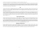
BACKWASHING FREQUENCY SCHEDULES MODELS: APIR075M, APIR075S MCA0750, MCA0751, MCA0750M, MCA0751M Persons in Family MODELS: APIR100M, APIR100S, MCA1000, MCA1001, MCA1000M, MCA1001M Persons in Family IRON CONTENT - (PPM) IRON CONTENT - (PPM) 2 4 6 8 10 12 14 16 18 20 1 1 1 1 1 1 1 1 1 1 1 2 1 1 1 1 1 2 2 2 2 2 4 3 1 1 2 2 2 2 3 3 3 3 1 1 2 2 2 3 3 4 4 4 2 4 6 8 10 12 14 16 1 1 1 1 1 1 1 1 2 2 1 1 1 2 2 2 2 3 3 1 1 2 2 2
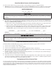
HOW TO SET TIME CONTROL 24 HOUR GEAR. SERVICE POSITION INDICATOR. MANUAL BACKWASH KNOB. 7 2 1 11 11 5 6 10 9 8 7 3 4 AM 6 7 3 5 4 12 12 2 8 2 4 7 7 9 1 2 E M Y TI f DA o 6 PM 6 10 12 1 3 7 TO MANUALLY START CYCLETURN KNOB CLOCKWISE. 5 5 4 3 1 PM 6 11 12 AM 6 5 10 11 5 TO SET TIME OF DAYPRESS RED BUTTON AND TURN LARGE DIAL UNTIL TIME IS AT ARROW. 9 10 4 4 8 8 9 3 E M Y TI f DA o TO MANUALLY START CYCLETURN KNOB CLOCKWISE.
HOW TO SET THE BACKWASH CYCLE PROGRAM: The backwash cycle program on your filter has been factory preset. However, portions of the cycle or program may be lengthened or shortened in time to suit local conditions. To expose cycle program wheel, grasp timer in upper left-hand corner and pull, releasing snap retainer and swing timer to the right. To change the backwash cycle program, the program wheel must be removed. Grasp program wheel and squeeze protruding lugs towards center, lift program wheel off timer.
SECTION 5: PLUMBING SYSTEM CLEAN-UP IMPORTANT NOTE The following procedures are guidelines only but have proven successful in most instances. Under no circumstances should any procedure outlined below be followed if contrary to the appliance manufacturer’s instructions. Should there be any questions concerning the advisability of performing a procedure, it is strongly recommended the manufacturer’s authorized service outlet be consulted prior to performing the procedure.
SECTION 6: MAINTENANCE Periodic media replenishment will be required if your raw water has a pH below 7 and/or a manganese content over 0.2 ppm. The frequency of replenishment will depend on raw water pH; hardness; iron; manganese; amount of water used; and the size of the filter selected. Should your raw water have a low pH, it is recommended that you check the media level every 6-12 months. To check the level follow these steps: 1) Place light behind mineral tank and observe media level.
Cleaning The AR-1 Air Release Vent The AR-1 may accumulate dirt in the seat area of the float assembly, which may cause the vent to malfunction. Periodic cleaning is recommended. The AR-1 may be serviced without depressurizing or draining the system. To clean the seat area, proceed as follows: 1) Turn the vent body to the right to the closed position, while holding the lower brass portion, isolating the vent from the system (See Figure 11).
SECTION 7: TROUBLESHOOTING PROBLEM A. B. C. D. CAUSE Water clear when 1. drawn, turns red upon standing (Stain producing) 2. Insufficient air-draw by Hydro-Charger. 1. Check Hydro-Charger adjustment. If unable to adjust for long enough draw, check pumping rate. Bypass open or leaking. 2. Close bypass valve and/or repair as necessary. 3. Filter bed overloaded with precipitated iron due 3.
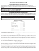
SECTION 8: SPECIFICATION & OPERATING DATA ITEM MCA0751 MCA0751M APIR075S APIR075M MCA1001 MCA1001M APIR100S APIR100M MCA1501 MCA1501M MCA2001 MCA2001M APIR200S APIR200M MCA3001 MCA3001M 0.75 (0.02) 1.0 (0.03) 1.5 (0.04) 2.0 (0.06) 3.0 (0.08) Gravel Underbed, lbs. (kg) 9 (4.1) 13 (5.9) 13 (5.9) 18 (8.2) 26 (11.8) Nominal Capacity, (ppm-gal) 22,500 30,000 45,000 60,000 90,000 Flow Rates, gpm (lpm) (2) Continuous (no duration limit) Service (10 min. or less) 2.0 (7.6) 4.0 (15.1) 3.
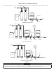
COMPONENT PARTS LIST Ref No.
CEC1000 SERIES BACKWASH CONTROL 8-3
ONLY THOSE PARTS CIRCLED IN DRAWING ON PREVIOUS PAGE AND/OR LISTED BELOW ARE STOCK ITEMS. ALL OTHERS ARE SPECIAL ORDER, NON-RETURNABLE. BACKWASH CONTROL 12 Day Timer REF. PART NO. A 60049/18706X 60049/18706-02X DESCRIPTION B 10090x Adapter Coupling Assy. (Incl. 2 ea. Ref Items 18-33, E & F) (Specify Model) C 10070 Control Valve Body Assy. (Incl. Ref Items 18-33, E & F) (Specify Model) D 60705 Drain Line Flow Control Assy. (Specify Size) E 60121C F 60090 1” Bypass Valve Assy. (Incl.
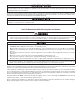
WIRING DIAGRAM FOR VALVE DRIVE MOTOR AND TIMER CEC1000 SERIES VALVES TIMER MOTOR BL AC K VALVE MOTOR BL AC K PROGRAM WHEEL PROGRAM RE-SET SWITCH DRIVE CAM SWITCH BLACK RAPID RINSE SERVICE CAM RED BLUE SERVICE CAM SWITCH BRINE TANK FILL RAPID RINSE BRINE AND RINSE BRINE & RINSE GREEN BACKWASH BLACK RED YELLOW BROWN BACKWASH BROWN DRIVE CAM YELLOW SERVICE BLACK BLACK BLACK WHITE BLUE WHITE PLUG-120 V.-A.C.
Limited Warranty Please read and complete the following warranty and mail the bottom half within 10 days of purchase CUNO Incorporated warrants to the original purchaser-consumer of its Product that it is free of defects in materials and workmanship. Any defect, malfunction, or other failure of this product to conform to this Warranty will be remedied by CUNO in the manner provided below.
CUNO is a trademark of 3M Company used under license. © 2007 3M Company. All rights reserved.