
Operating instructions

a. Make certain no water is being drawn. Open spigot nearest pressure tank. When pump starts, close spigot
and measure time (in seconds) to refi ll pressure tank (when pump shuts off). This fi gure represents Cycle
Time.
b. With the pressure tank full, draw water into a container of known volume, measure the number of gallons
drawn until the pump starts again. This is the Draw-Down. Divide this fi gure by Cycle Time and multiply the
result by 60 to arrive at the Pumping Rate in gallons per minute (gpm). To aid in your calculation, insert the
data in the following formula:
Draw-Down _______(gallons) ÷ Cycle Time ________(seconds) x 60 = Pumping Rate _______ (gpm)
Example: Cycle Time is 63 seconds; Draw-Down is 8 gallons, then Pumping Rate equals:
8 gallons ÷ 63 seconds x 60 = 7.8 gpm
NOTE: The addition of the Hydro-Charger to the pumping system or plumbing and other water treatment devices
(such as an acid neutralizer) may reduce the fl ow rate at the drain to an inadequate level to properly backwash the
system. If you are uncertain whether your fl ow rate is adequate, contact your dealer BEFORE installing your Chem-
Free System so that corrective action, if required, may be taken.
Locate Water Conditioning Equipment Correctly: Failure to do so may result in property damage and
will void warranty.
Select the location of your fi lter unit with care. Various conditions which contribute to proper location are as follows:
1) Locate as close as possible to water supply source.
2) Locate as close as possible to a fl oor or laundry tub drain.
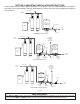
3) Locate in correct relationship to other water conditioning equipment (See Figures 1, 3 or 7 in Sec. 3)
4) Filters and softeners should be located in the supply line BEFORE the water heater. Temperatures above 100 °F (38°C)
damage fi lters and softeners and will void the factory warranty.
5) Do NOT install a fi lter or softener in a location where freezing temperatures may occur. Freezing may cause permanent
damage to this type of equipment and will also void the factory warranty.
6) Allow suffi cient space around the unit for easy servicing.
7) If your water source is a community water supply, a public water supply, or you wish to bypass water used for a
geothermal heat pump, lawn sprinkling, out-buildings or other high demand applications, refer to Figures 3 or 7 for
additional equipment required. Also refer to the Special Instructions on page 3-13.
The Importance of Your Pressure Tank:
The pressure tank found on private well systems becomes an integral part of the Chem-Free Iron Reduction System by provid-
ing necessary mixing and “residence time” to the “Hydro-Charged” water. While the Chem-Free Iron Reduction System will
perform satisfactorily with either a captive-air (bladder) type pressure tank or a standard air-to-water type with an air volume
control (air-relief valve), the bladder type requires more careful adjustment of the Hydro-Charger to prevent gasses from col-
lecting in the pressure tank and the head area of the fi lter tank.
IMPORTANT: A properly sized pressure tank of either style will require a minimum pump cycle of 60
seconds to refi ll from the well pump on-to-off pressure settings.
Under more severe operating conditions (low pH, high iron, manganese, and small concentrations of sulfur), a standard air-
to-water type pressure tank with an air-relief valve MUST be used (if a bladder type tank is already in place, do not remove it,
install the air-to-water pressure tank between the Hydro-Charger and the bladder type tank).
If your pressure tank (or any part of your water system) is not functioning properly, corrective action
MUST be taken before installation of your Chem-Free Iron Reduction System.
2-3
IMPORTANT NOTE
CAUTION