
Operating instructions

IMPORTANT NOTES
• The system should be installed on cold water lines only.
• SHUT OFF FUEL SUPPLY TO WATER HEATER after water is shut off.
• Failure to follow instructions may void warranty.
• The INLET and OUTLET of other water treatment equipment will vary depending on the the control valve brand used.
Please verify the INLET and OUTLET openings on each control valve before making the plumbing connections.
• Do not apply heat near Hydro-Charger, as damage may occur. On badly scaled, older plumbing systems, it may be ad
vantageous to install a WYE STRAINER to help prevent plugging of the Hydro-Charger nozzle with scale or debris.
The use of a WYE STRAINER must precede the hydrocharger on the inlet side by a MINIMUM OF 10”.
• If existing water system includes a captive-air type pressure tank (bladder) and it is desirable to install an additional
air to water type with an air release (not as a split steam type installation) install an air to water type pressure tank
between the Hydro-Charger and the existing captive air type pressure tank.
• Before proceeding with Hydro-Charger installed, re-verify adequate pumping rate pumping by following the procedure
described in SECTION 2. After verifi cation of adequate fl ow, depressurize system as described previously.
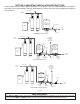
• If installation is to be split streamed prior to fi lter vessel or is it a public water supply (see fi gure 1), or refer to special
instructions on page 3-13.
• When the duration of the suction is too long, the cold water may have a milky appearance caused by excess air in the
water system. Correct this condition by reducing the duration of suction. This condition is commonly associated with
bladder type pressure tanks. In extreme cases where elimination of excess air prevents system from performing satis
factorily, it may be necessary to install an air to water pressure tank with an air release valve.
• Due to the nature of the Chem-Free Iron Reduction media, on start up it sometimes requires 2 or 3 days for the
Chem-Free Iron Filter to reduce Iron and Manganese below staining levels. Do not be alarmed if this occurs. During
the initial start up and subsequent fi rst couple automatic regeneration cycles, a small amount of fi ne white and beige
media may be observed in the drain water and or drain area. This is normal and benefi cial for the effi cient operation of
your Chem-Free Iron Filter Reduction System.
• Failure to set PRESSURE SWITCH as described above will NOT allow proper closing of SOLENOID VALVE during
periods of low system pressure. Improper function of SOLENOID VALVE will cause total failure of system.
• The Backwashing Frequency Schedules are based on average water consumption rates and are merely guides. They
are NOT intended to be used if water is used by outside spigots, a swimming pool, geothermal heat pump, or other
high water usage devices or activities. If your application includes any of these, and you have already determined
your model Chem-Free System is capable of handling the fl ow rates involved, refer to the next paragraph for
instructions on setting Backwash Frequency.
•
Replenishment of pH adjusting component of media may be required periodically, the frequency of which
is dependent on raw water pH, manganese concentration and water consumption rate. Consult dealer
for more information.
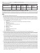
• For satisfactory performance, indicated durations should not be exceeded. Flow rates specifi ed are
adequate for normal residential applications. Do not use Service or Peak fl ow rates when sizing
commercial applications or if treated water is to supply a geothermal heat pump, swimming pool, etc.
(contact dealer before selecting equipment). Service fl ow rates have been tested against NSF Standard 42
and have a rated pressure drop of less than 10 psi.
• For system to operate properly, pumping rate of well pump MUST be suffi cient to backwash unit at rate
specifi ed.
• Service Pipe size is 3/4” on models not shown above: MCIF0750, 0750M, 1000, 1000M, 1500, 1500M,
2000, 2000M, 3000 and 3000M.