
Operating instructions
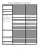

Installation must comply with state and local plumbing codes. Failure to follow installation, operation
and maintenance instructions may result in property damage due to leakage and will void warranty.
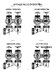
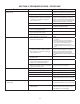
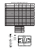
Special Instructions For Split-Stream and Public Water Supply Type Installation:
For SPLIT-STREAM type installation, a secondary PRESSURE TANK must be installed as in Figure 1. On PUBLIC WATER
SUPPLY type installations, a PRESSURE TANK must be installed as in Figure 1. It is recommended in both applications
to use a standard air-to-water type pressure tank with air volume control (air release valve). The pressure tank should be
of same capacity as would normally be installed if water systems were a standard private well type. Also note both ap-
plications require a NORMALLY-CLOSED SOLENOID VALVE. Follow standard installation procedures above with
following additions and modifi cations.
1) Install PRESSURE TANK (SECONDARY PRESSURE TANK in Figure 1) as indicated by appropriate diagram.
2) Install NORMALLY-CLOSED SOLENOID VALVE, 110/120V, 60Hz after water meter and AFTER a line split for
untreated water (if there is one).
3) On both types installation, install HYDRO-CHARGER between PRESSURE TANK (SECONDARY PRESSURE TANK
on SPLIT-STREAM type installation) and NORMALLY-CLOSED SOLENOID VALVE.
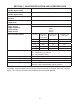
4) Install PRESSURE SWITCH after HYDRO-CHARGER and wire it to SOLENOID VALVE (SECONDARY
PRESSURE SWITCH on SPLIT-STREAM) Set HIGH pressure on PRESSURE SWITCH (which controls opening
and closing of SOLENOID VALVE) 2 to 3 psi LOWER than LOW pressure on PRIMARY PRESSURE SWITCH.
EXAMPLE: If PRIMARY PRESSURE SWITCH is set at 40/60 psi, set SECONDARY PRESSURE SWITCH
at 20/38 psi.
For PUBLIC WATER SUPPLY type installations, contact your local water department or plant operator and ask what the normal
LOW system pressure is. Set HIGH pressure on PRESSURE SWITCH 2 to 3 psi LOWER than this fi gure.
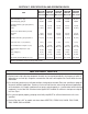
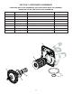
Special Service Instructions:
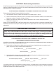
Under normal circumstances removal of valve should never be required. However, if it must be removed, it can be done by
disassembling the quick release clamp, by removing latch. Pressure should be relieved before attempting any disassembly.
Upon reassembly, all O-rings should be lubricated with silicone grease. Reassemble clamp as shown in Figure 7. MAKE SURE
ARROWS ON LATCH SIDE OF CLAMP ARE ALIGNED.
Figure 7
3-13
IMPORTANT NOTE
CAUTION
Failure to set PRESSURE SWITCH as described above will NOT allow proper closing of SOLENOID
VALVE during periods of low system pressure. Improper function of SOLENOID VALVE will cause total
failure of system.