
Operating instructions

Step 9
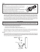
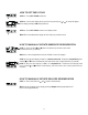
Fitting Installation Instructions
1) The installation fi ttings are designed to accommodate minor plumbing line and
fi ttings.
2) Thread tape is the only type of thread sealant allowed to be used; the use of paste
of any kind will void the factory warranty. Do not let the connection fi ttings sup-
port the plumbing, properly support the plumbing as required.
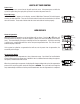
3) Slide the nut on fi rst (closed and against the threads), then slip ring onto the fi t-
ting, ensuring it set correctly in groove, then the O-ring last. Use Silicone lubricant
to allow for easier insertion of parts into one another.
4) Hand tighten the nut only, the use of pliers or wrenches of any type will void the
factory warranty and may cause an unexpected failure and water will leak in your home or facility.
1
3
2
4
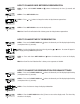
Use customer supplied fi ttings to adapt the drain line to the control valve. Support of the drain line is required to prevent
damage to the drain line elbow which could lead to a water leak in the dwelling. Suitable drain line material can be Copper,
PVC or CPVC pipe or PE tubing can be used to adapt to the ¾ NPT threads on the drain elbow for long or high drain lines.
Use only thread sealing tape to seal the threads, hand tighten the threaded joint. To utilize polyethylene tubing as a drain
line, remove the supplied nut and fi nd the insert that was shipped in the parts kit box. Slide the nut over the polyethylene
tubing and insert the sleeve into the tubing. Slide the end of the tubing into the elbow, using your hand thread the nut onto
the elbow and hand tighten only. No thread tape is required to seal the threads with compression fi ttings.
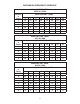
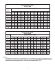
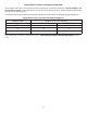
Typical examples of proper drain line diameters and lengths are:
1/2” ID up to 15 feet when discharge is lower than the inlet.
5/8” ID up to 15 feet when discharging is slightly higher than the inlet.
3/4” ID when drain is 25 feet away and not higher than 4 feet above control valve.
Avoid installing drain line overhead or using fl exible vinyl tubing, either may result in the fi lter not operating properly in
reducing iron, manganese or turbidity. Some areas prohibit the use of fl exible drain lines. Check with the local code of-
fi cials prior to installation to ensure you conform to local, state and national plumbing codes.
Step 10
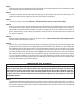
Position the DRAIN LINE over the waste drain pipe and secure fi rmly. To prevent back siphoning of sewer water or grey
water, provide an air gap of at least two inches or 2 times the pipe diameters between the end of drain line tubing and
waste drain (Figure 6). Do not raise the DRAIN LINE more than 10 feet above the fl oor. Check with local code offi cials to
ensure you conform to local, state and national plumbing codes.
3-5
Overtightening could cause the nut to fail unexpectedly and cause water damage to the dwelling.
AIR GAP
2" REF
EQUIPMENT
DRAIN LINE
DRAIN
Figure 6: DRAIN
CAUTION
Figure 5