
Operating instructions

3-4
OFF
OFF
OFF
OFF
OFF
OFF
OFF
OFF
OFF
OFF
OFF
OFF
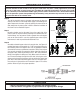
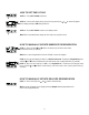
Supply Water
Enters
Supply (Untreated)
Water Exits
Supply Water
Enters
Treated Water
Exits
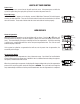
NORMAL OPERATION BYPASS OPERATION
BYPASS VALVE
INOU
T
CONTROL VALVE BO
DY
DRAIN LINE FLOW
CONTROL ASSEMBL
Y
Figure 3
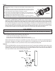
When the duration of the suction is too long, the cold water may have a milky appearance caused by
excess air in the water system. Correct this condition by reducing the duration of suction. This condi-
tion is commonly associated with bladder type pressure tanks. In extreme cases where elimination of
excess air prevents system from performing satisfactorily, it may be necessary to install an air to water
pressure tank with an air release valve.
Figure 4
IMPORTANT NOTES
CAUTION
• Do not use torches or other heat sources near plastic fi ttings.
• Take care when using pliers or pipe wrenches to tighten plastic fi ttings.
Step 6
Turn off the electrical source to the water well pump or the close the
water shut off valve on a municipal water supply to the dwelling once
again. Depressurize the water system by opening the nearest faucet to
drain water from the water system in order to allow the installation of
the Chem-Free Iron Reduction System.
Step 7
Determine location and cut the water line on the supply side of the
pressure tank as required to fi t the plumbing to the control valve con-
nection fi ttings. You may want to install a separate three valve bypass
prior to the control valve in case the supplied bypass valve requires
maintenance in order to provide undisturbed water use.
Step 8
Assemble and attach bypass valve to the control valve. See Figure 3 if
needed. Next locate and assemble the 1” NPT connection fi ttings be-
fore attaching them to the bypass valve. Use the appropriate method
of connection to ensure a permanent connection. Please refer to fi gure
5 to correctly assemble the connection fi ttings. Install the fi tting into
the bypass valve, attach the plumbing to the 1” NPT male connection
fi ttings, hand tighten the fi ttings nuts only. Make certain the water en-
ters inlet and discharges through the outlet side of the bypass valve.
Arrows can be viewed on the bypass valve to confi rm the correct fl ow
path. At this time make certain the bypass valve is in the bypass posi-
tion and leave in that position until instructed to place in the service
position. Refer to Figure 3 for proper operation.