
Operating instructions

3-2
NOTE: Have you read “ Section 4”, PLUMBING SYSTEM CLEANUP, for instructions on some procedures that may
need to be performed fi rst?
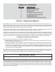
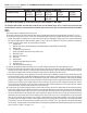
GRAVEL AND CHEM-FREE MEDIA SCHEDULE
Unit Model Number APIF075
MCIF0751
APIF100
MCIF1001
APIF150
MCIF1501
APIF200
MCIF2001
APIF300
MCIF3001
Chem-Free Filter Media MC-075P MC-10P MC-10P
MC-050P
MC-10P (2) MC-10P (3)
NOTE: If you ordered an “M” model Chem-Free Free Iron Filter, Iron Reduction System the fi lter pack me-
dia would be designated by an M at the end of the part number i.e. MC-10MP.
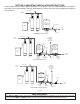
To load the fi lter media into the fi lter tank please use the follow steps. This is necessary to ensure that
the distributor tube has not been pulled up when the control valve was removed from the top of the fi lter
tank.
Step 1
a) Remove from the shipping carton the fi lter unit
b) Carefully remove the control valve from the fi lter vessel by releasing the latch on the clamping collar (see fi gure 7 on 3-13).
c) Set all items aside for future use. Ensure that the following items have been shipped entirely with the unit to allow for
proper and complete installation. If any item is missing or has been damaged in transit contact our technical department
for help and replacement at 866-693-2543 (option 1) from 7:30 am to 4:30pm EST. Please be prepared to supply the
model and serial number when you call should you need help.
i. Control valve
ii. Mineral tank (also a reducing bushing and fl anged adapter on MCIF3001 and APIF300)
iii. Bypass valve
iv. 1” Male NPT Connection Kit
v. Chem-Free Media (amount will vary by fi lter size)
vi. Distributor Tube
vii. Drain line assembly kit
viii. Parts bag
ix. Valve wrench
x. Installation and Operating Instruction
xi. Loading funnel
xii. Tube extension device and cap
d) Remove the distributor tube in the fi lter vessel, set aside and pour the gravel into a clean pail for later use.
e) Reinsert the distributor tube into the fi lter vessel and ensure the tube is centered in the tank; a dimple is in the center of
the fi lter vessel to help in doing so. Using the tube extension device and cap, cover the distributor tube opening to prevent
fi lter media and gravel from entering the distributor tube during the loading of the fi lter vessel.
f) Place the funnel provided, in the opening of the mineral tank to aid in loading the gravel and fi lter media. Pour the QC
gravel into the fi lter vessel slowly. While holding the distributor tube in place, shake the fi lter vessel from side to side gen-
tly, to aid in leveling the QC gravel. Do not allow gravel to get under the basket of the distributor tube during the loading
of gravel. If this happens, pour out the gravel and remove the distributor tube once again. Next locate the fi lter media and
slowly pour into the fi lter vessel. Again shake the fi lter vessel from side to side to aid in leveling the media. Next, using a
hose or clean pail, fi ll the fi lter vessel with water to saturate the fi lter media and expel any air that may be present, remove
the extension tube, cap and funnel, and save for future servicing.
g) Using a clean dry rag, wipe the opening of the mineral tank to remove any dust or residue from the opening to receive the
control valve. Apply silicone lubricant to the fi lter vessel fl anged opening and control valve O-rings that seal against the
fi lter vessel and pilot tube O-ring in the center of the control valve. Place the center of the control valve over the distribu-
tor tube and push down on the control valve until it contacts the fl ange on the fi lter vessel. Using one swift and even push
downward, seat the control valve into the opening of the fi lter vessel. Do not use a rocking motion to seat the control
valve as this could roll or pinch the O-ring, causing a leak between the control valve and fi lter vessel. Place the clamp
assembly around the fl ange of the fi lter vessel and the control valve, paying particular attention to the proper orientation
of the clamp. To secure the clamp in place install the latch. Refer to Figure 7 on 3-13 to determine the proper orientation
for the clamp. The latch needs to be installed with the smaller opening toward the clamp. Attach the bypass to the control
valve as shown in Figure 7 on page 3-13.