Chem-Free IRON REDUCTION SYSTEMS INSTALLATION AND OPERATING INSTRUCTIONS Chem-Free Iron Filter Models Aqua-Pure® Models: APIF075 APIF100 APIF150 APIF200 APIF300 APIF075M APIF100M APIF150M APIF200M APIF300M MacCLEAN Models: MCIF0751 MCIF1001 MCIF1501 MCIF2001 MCIF3001 MCIF0751M MCIF1001M MCIF1501M MCIF2001M MCIF3001M a 3M company (Installer, please leave with homeowner.) IN318 0107 CUNO Incorporated 400 Research Parkway Meriden, CT 06450 U.S.A.
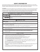
SAFETY INFORMATION Read, understand, and follow all safety information contained in these instructions prior to installation and use of the CUNO MCIF & APIF Series Residential Chem-Free Iron Reduction Filter. Retain these instructions for future reference. Failure to follow installation, operation and maintenance instructions may result in property damage and will void warranty.
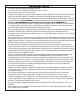
IMPORTANT NOTES • • • • • • • • • • • • The system should be installed on cold water lines only. SHUT OFF FUEL SUPPLY TO WATER HEATER after water is shut off. Failure to follow instructions may void warranty. The INLET and OUTLET of other water treatment equipment will vary depending on the the control valve brand used. Please verify the INLET and OUTLET openings on each control valve before making the plumbing connections. Do not apply heat near Hydro-Charger, as damage may occur.
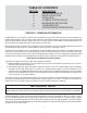
TABLE OF CONTENTS SECTION 1 2 3 4 5 6 7 DESCRIPTION GENERAL INFORMATION BEFORE INSTALLATION INSTALLATION PLUMBING SYSTEM CLEAN-UP BACKWASHING INSTRUCTIONS TROUBLESHOOTING SPECIFICATION AND OPERATING DATA SECTION 1: GENERAL INFORMATION Congratulations on your purchase of a Chem-Free Iron Reduction System! The Chem-Free System reduces dissolved, precipitated and bacterial iron from your water supply.
SECTION 2: BEFORE INSTALLATION Inspecting And Handling Your Filter: Inspect the equipment for shipping damage. If damaged, notify the transportation company and request a damage inspection. Handle the filter with care. Damage can occur if dropped or set on sharp, uneven projections on the floor. Do not turn the filter upside down. Installation must comply with state and local laws and regulations.
pH The pH of water measures its acidity. Water with a pH of less than 7.0 is acidic, above 7.0 it is alkaline, and a pH of 7.0 is neutral. The lower the pH value, the greater the acidity, and the higher the pH value, the more alkaline. Acidic water (pH less than 7.0) is corrosive to pipes, appliances, etc. A pH of 7.0 or higher facilitates iron reduction, which is why the Chem-Free System is designed to increase the pH when it is less than 7.0.
a. Make certain no water is being drawn. Open spigot nearest pressure tank. When pump starts, close spigot and measure time (in seconds) to refill pressure tank (when pump shuts off). This figure represents Cycle Time. b. With the pressure tank full, draw water into a container of known volume, measure the number of gallons drawn until the pump starts again. This is the Draw-Down. Divide this figure by Cycle Time and multiply the result by 60 to arrive at the Pumping Rate in gallons per minute (gpm).
CAUTION Improper installation and use may result in property damage due to water leakage. Facts To Remember While Planning Your Installation: 1) All installation procedures MUST conform to local and state plumbing codes. 2) All water MUST pass through the Hydro-Charger Assembly, pressure tank and the Chem-Free Filter System, or refer to the special instructions for a split-stream installation in Section 3.
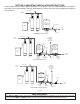
SECTION 3: IMPORTANT INSTALLATION INSTRUCTIONS Proper installation sequence of water conditioning equipment is very important. Refer to the following diagram for your particular water supply. Failure to follow installation, operation, and maintenance instructions may result in property damage due to leakage and will void warranty. IRON FREE WATER IRON FREE SOFT WATER PRESSURE HYDRO-CHARGER TANK BRINE MAKER RAW WELL WATER SOFTENER IRON FILTER PRESSURE SWITCH.
NOTE: Have you read “ Section 4”, PLUMBING SYSTEM CLEANUP, for instructions on some procedures that may need to be performed first? Unit Model Number Chem-Free Filter Media GRAVEL AND CHEM-FREE MEDIA SCHEDULE APIF075 APIF100 APIF150 APIF200 MCIF0751 MCIF1001 MCIF1501 MCIF2001 MC-075P MC-10P MC-10P MC-10P (2) MC-050P APIF300 MCIF3001 MC-10P (3) NOTE: If you ordered an “M” model Chem-Free Free Iron Filter, Iron Reduction System the filter pack media would be designated by an M at the end of the part numbe
Step 2 Shut off water at main supply. On a PRIVATE WELL SYSTEM turn off the power to the WELL PUMP and drain PRESSURE TANK. Make certain all water pressure has been relieved from complete water system by opening nearest faucet to drain water system. SHUT OFF FUEL SUPPLY TO WATER HEATER OR BOILER. Step 3 Cut main supply line as required to fit Hydro-Charger in plumbing between well pump and pressure tank (Hydro-Charger may be installed in a vertical or horizontal position).
IMPORTANT NOTES When the duration of the suction is too long, the cold water may have a milky appearance caused by excess air in the water system. Correct this condition by reducing the duration of suction. This condition is commonly associated with bladder type pressure tanks. In extreme cases where elimination of excess air prevents system from performing satisfactorily, it may be necessary to install an air to water pressure tank with an air release valve.
Step 9 Fitting Installation Instructions 1) The installation fittings are designed to accommodate minor plumbing line and fittings. 2) Thread tape is the only type of thread sealant allowed to be used; the use of paste 1 of any kind will void the factory warranty. Do not let the connection fittings sup2 port the plumbing, properly support the plumbing as required.
Step 11 Plug the control valve into a properly grounded 110/120V 60 Hz non switched electrical outlet. Check with your local code enforcement office to determine if it meets local codes. Step 12 Turn back on the power source to well pump and slowly open the shut off valve to pressurize the water system. If on a public or community water supply open the main shut off valve to the dwelling. Step 13 Set the time of day by referring to Section 3 INSTALLATION “How to set the Time of Day”.
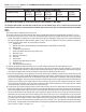
BACKWASH FREQUENCY SCHEDULE Models MCIF 0751, 0751M APIF 0751, 0751M Persons in Family 1 2 3 4 IRON CONTENT - (PPM) 2 12 12 12 12 4 12 12 12 6 6 12 12 6 6 8 12 6 6 4 10 12 6 6 4 12 12 6 4 3 14 12 6 4 3 16 12 4 3 2 5 12 6 6 4 3 3 2 2 6 12 6 4 3 3 2 2 1 Models MCIF 1001, 1001M APIF 100, 100M Persons in Family 1 2 3 4 5 IRON CONTENT - (PPM) 2 4 6 8 10 12 14 16 12 12 12 12 12 12 12 12 12 12 12 12 6 6 6 12 6 6 6 6 12 6 6 4 4 12 6 4 4 3 12 6 4 4 3 12 6 4 3 3 6 12 6 6
Models MCIF 2001, 2001M, APIF200, 200M Persons in Family 1 2 3 4 5 IRON CONTENT - (PPM) 5 12 12 12 12 12 10 12 12 12 12 6 12 12 12 12 6 6 14 12 12 6 6 6 16 12 12 6 6 4 18 12 12 6 6 4 20 12 12 6 6 4 22 12 6 6 4 4 24 12 6 6 4 4 26 12 6 6 4 3 28 12 6 4 4 3 30 12 6 4 4 3 6 7 8 9 10 12 12 12 6 6 6 6 6 4 4 6 4 4 4 3 4 4 4 3 3 4 3 3 3 3 4 3 3 3 2 4 3 3 2 2 3 3 2 2 2 3 2 2 2 2 3 2 2 2 1 2 2 2 1 1 2 2 2 1 1 Models MCIF 3001,3001M APIF 300, 300M IRON CONTENT - (PPM) Persons in Family 1 2 3
HOW TO SET TIME OF DAY STEP 1 - Press SET HOUR and release. STEP 2 - Set the clock display to the closest hour by pressing the or . An arrow will appear in the display pointing to PM during PM hours. STEP 3 - Press SET HOUR to return to the display mode. Note: After an extended power outage the time of day may need to be reset. HOW TO MANUALLY INITIATE IMMEDIATE REGENERATION STEP 1 - Press and hold and buttons simultaneously until valve motor starts (usually about three (3) seconds).
HOW TO CHANGE DAYS BETWEEN REGENERATION STEP 1 - Press and hold SET HOUR and release. buttons simultaneously for three (3) seconds and STEP 2 - Press SET HOUR button. STEP 3 - Press or buttons to change the number of days between regenerations. STEP 4 - Press SET HOUR to return to the display mode. Note: Your Chem-Free Iron Reduction filter is factory preset for 4 days between regenerations. HOW TO CHANGE TIME OF REGENERATION STEP 1 - Press and hold SET HOUR and (usually about three (3) seconds).
Control Valve Function and Cycles of Operation The AC adapter comes with a 15 foot power cord that is designed for use with the control valve. The AC adapter is for dry location use only. If the power goes out, only the time of day needs to be reset. All other settings are permanently stored in the non-volatile memory. The following chart shows the time for the backwash and rapid rinse cycles for the three available programming options.
HOW TO SET TIMER CONTROL Power Loss If the power goes out, current time of day will need to be reset. If the power goes out while the system is regenerating, the cycle picks up where it was when the power went out. Error Message If “E1” “E2” or “E3” appears on the display, contact CUNO Water Treatment Technical Support Services @1-866-692-2543. These are error codes and will need to be resolved before the control valve will function. These codes indicate that the control valve did not function properly.
CAUTION Installation must comply with state and local plumbing codes. Failure to follow installation, operation and maintenance instructions may result in property damage due to leakage and will void warranty. Special Instructions For Split-Stream and Public Water Supply Type Installation: For SPLIT-STREAM type installation, a secondary PRESSURE TANK must be installed as in Figure 1. On PUBLIC WATER SUPPLY type installations, a PRESSURE TANK must be installed as in Figure 1.
Figure 8 Figure 9 Figure 10 Figure 11 3-14
SECTION 4: MAINTENANCE The following procedures are guidelines only but have proven successful in most instances. Under no circumstances should any procedure outlined below be followed if contrary to the appliance manufacturer’s instructions. Should there be any questions concerning the advisability of performing a procedure, it is strongly recommended the manufacturer’s authorized service outlet be consulted prior to performing the procedure.
SECTION 5: Backwashing Instructions Periodic Backwashing of the Chem-Free Filter System bed is required to flush out the entrapped iron that has accumulated. This procedure is performed automatically at 1:00 a.m. for a period of approximately 10 minutes and will not interfere with a softener regeneration, which is usually set for 2:00 a.m.
SECTION 6: TROUBLESHOOTING - CONTROL VALVE Problem 1. Timer does not display time of day Cause Solution a. AC adapter unplugged a. Connect power b. No electric power at outlet b. Repair outlet or use working outlet c. Defective AC adapter c. Replace C Adapter d. Defective PC board d. Replace PC board 2. Timer does not display correct time of day a. Switched outlet a. Use an unswitched outlet b. Time of day not set correctly b. Reset time of day 3.
SECTION 6: TROUBLESHOOTING - FILTER UNIT Problem 1. Water CLEAR when drawn, turns RED upon standing (Stain producing) 2. Water RED when drawn from tap 3. Excessive pressure loss through filter 4. “Milky” or “bubbly” water (Appears to contain small bubbles) Cause Solution a. Insufficient air-draw by Hydro-Charger. a. Check Hydro-Charger adjustment. If unable to adjust for long enough draw, check pumping rate. b. Bypass open or leaking b. Close bypass valve and/or repair as necessary. c.
SECTION 7: VALVE SPECIFICATION AND OPERATING DATA Maximum Service Flow Rate: Includes Bypass Valve 27 gpm (102.2 lpm) @15 psig (103 kPa) drop Maximum Backwash Flow Rate: Includes Bypass Valve 27 gpm (102.2 lpm) @15 psig (103 kPa) drop Minimum/Maximum Operating Pressure: 20 psi (138 kPa) - 125 psi (862 kPa) Minimum/Maximum Operating Temperature: 40°F (4.4°C) - 110°F (43.3° C) U.S. AC Adapter: Supply Voltage Supply Frequency Output Voltage Output Current Drain Line Flow Control 120 V. AC 60 Hz 12 V.
SECTION 7: SPECIFICATION AND OPERATING DATA APIF075 APIF100 APIF175M APIF100M MCIF0751 MCIF1001 MCIF0751M MCIF1001M ITEM APIF150 APIF150M MCIF1501 MCIF1501M APIF200 APIF300 APIR200M APIF300M MCIF2001 MCIF3001 MCIF2001M MCIF 3001M Media Volume, cu. ft. (cu. mtr.) (Note 1): Gravel Underbed, lbs. (kg) Nominal Capacity, ppm-gal. 0.75 (0.02) 9 (4.1) 22,500 1.0 (0.03) 13 (5.9) 30,000 1.5 (0.04) 13 (5.9) 45,000 2.0 (0.06) 18 (8.2) 60,000 3.0 (0.08) 26 (11.
SECTION 7: COMPONENT PARTS LIST MCIF0751 MCIF0751M APIF075S APIF075M MCIF1001 MCIF1001M APIF100S APIF100M MCIF1501 MCIF1501M APIF150S APIF150M MCIF2001 MCIF2001M APIF200S APIF200M MCIF3001 MCIF3001M APIF300S APIF300M Control Valve, Complete, Less Bypass Valve (MCIF Series) W217420-003-0C W217530-003-0C W217530-003-0C W217750-003-0C W217000-003-0C W217000-003-0N Ref. No.
SECTION 7: COMPONENTS ASSEMBLIES CHEM-FREE IRON FILTER ASSEMBLIES AND COMPONENTS DRIVE CAP ASSEMBLY, DOWNFLOW PISTON, AND SPACE STACK ASSEMBLIES Reference No. Part No.
SECTION 7: FRONT COVER AND DRIVE ASSEMBLY Reference No. Part No. Description Quantity 1 V3175TC-01 Time Clock Front Cover Assembly 2 V3107-01 Motor 1 3 V3106-01 Drive Bracket & Spring Clip 1 4 V3108TC Time Clock PC Board 1 5 V3110 Drive Gear 12 x 36 1 6 V3109 Time Clock Cover 1 V3002TC Time Clock Drive Assembly 1 V3186 AC Adapter 110V - 12V 1 NOT SHOWN 1 Drawing number parts 2 through 6 may be purchased as a complete assembly, part V3202.
SECTION 7: QUICK CONNECT BYPASS Part Number V3006 Reference No. Part No.
SECTION 7: INSTALLATION FITTING AND ASSEMBLIES Quick Connect Assemblies Part # V3007-02 1” Copper Brass Sweat Adapter Reference No. Part No. Description: 1” Brass Sweat Assembly Quantity 1 V3151 1” Quick Connect Nut 2 2 V3150 1” Quick Connect Split Ring 2 3 V3105 1” Quick Connect O-Ring 215 2 4 V3188 1” Quick Connect Brass Sweat Assembly 2 4 3 1 2 Part # V3007-04 1” Plastic Male NPT Assembly Reference No. Part No.
Reference No. 1 2 3 4 5 6 7 7 7 7 Part No. Description H4615 PKP10T58S-BLK V3192 V3158-01 V3163 V3159-01 V3162-042 V3162-053 V3162-075 V-3262-100 Elbow Locking Clip 5/8” Insert Sleeve Quick Connect 3/4” Drain Elbow Nut Quick Connect 3/4” Drain Elbow O-ring 019 Drain Line Flow Control Retainer Assembly 4.2 gpm Drain Line Flow Control Button 5.3 gpm Drain Line Flow Control Button 7.5 gpm Drain Line Flow Control Button 10.
SECTION 8: MAINTENANCE Depending on your water quality, it may be necessary to perform maintenance on your filter system in order to ensure continued performance. This is to both low pH, high manganese and the sacrificial nature of the filter media. The severity of your pH or the amount of water used will determine how often the filter will need to be serviced. To correct this condition, it will be necessary to add MPH adder to the filter bed.
8) Pour the recommended amount of MPH adder into the filter media and add water back to filter to expel any air pockets in the filter vessel. 9) Reinstall the control valve back on top of filter vessel. You may want to apply some silicone lubricant to the O-rings, distributor tube and the inside of the filter vessel opening to facilitate for easier installation.
Limited Warranty Please read and complete the following warranty and mail the bottom half within 10 days of purchase CUNO Incorporated warrants to the original purchaser-consumer of its Product that it is free of defects in materials and workmanship. Any defect, malfunction, or other failure of this product to conform to this Warranty will be remedied by CUNO in the manner provided below.