Authorized Technician TECHNICAL MAINTENANCE MANUAL LEGEND LX SECOND STAGE Copyright ©2000 Aqua Lung America, Inc. Rev.
Legend LX Second Stage Service Manual Contents COPYRIGHT NOTICE...............................................................................................................................................3 INTRODUCTION .......................................................................................................................................................3 WARNINGS, CAUTIONS, & NOTES...........................................................................................................
COPYRIGHT NOTICE An Official Inspection consists of: This manual is copyrighted, all rights reserved. It may not, in whole or in part, be copied, photocopied, reproduced, translated, or reduced to any electronic medium or machine readable form without prior consent in writing from Aqua Lung America. It may not be distributed through the internet or computer bulletin board systems without prior consent in writing from Aqua Lung America. ©2002 Aqua Lung America, Inc. 1.
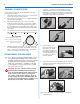
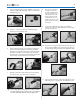
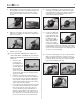
Legend LX Second Stage Service Manual GENERAL CONVENTIONS 1. Using two ¹¹₁₆” wrenches, hold the retaining nut (15) stationary while turn the hose swivel counterclockwise. Remove the o-ring (38) from inside the hose swivel. Exercise caution not to scratch the o-ring groove. Remove the o-ring (42) from the male end of the hose. 2. Pull back the two hose protectors (39 & 41) and inspect the hose crimps. The crimps should be free from damage and the hose should not be pulling out of the crimp.
4. 5. Using the Retaining Ring Tool (pn 129001), unscrew and remove the diaphragm retainer (5). Lift out the washer (6) and diaphragm (7). 8. Turn the knob clockwise (inward) one turn. The pin (24) should drop out. If the pin remains in the valve body, use a 1/16" dowel or punch to push it partially out, then use needlenose pliers to completely remove it from the valve body. 9. Unscrew the adjustment knob (34) and completely remove it from the valve body.
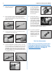
Legend LX Second Stage Service Manual 12. Remove the o-ring (22) from the valve body. 16. To remove the exhaust tee (14), submerge the box bottom with tee in hot water (approximately 125°F) for 2 to 3 minutes. Grasp the tee by one of its wings and pull it off the box bottom. 13. Insert a small 1/8” wooden dowel into the threaded end of the valve body and push out the shuttle valve assembly (26-30). Separate the shuttle valve assembly by pulling on each end. 17.
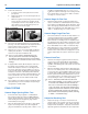
REASSEMBLY PROCEDURES 1. If the exhaust valve (13) was removed, thread the tail through the retaining hole on the outside of the box bottom until the barb engages on the inside. If it is a new valve, cut the excess stem with side cutters leaving approximately 5mm of the tail behind. 2. Soak the exhaust tee in hot water (~125°F) for 2 to 3 minutes. Install the exhaust tee (14) onto the flange on the outside of the box bottom.
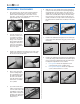
9. Legend LX Second Stage Service Manual Press the grip (34) onto the adjustment knob. Using the LX Tool, screw the plug (37) into the end of the adjustment knob. 12. While depressing the lever, insert the valve body through the venturi lever and into the box bottom. Be sure that the two index flats and the two lever feet engage the tabs molded into the box bottom. 13. Slide a new, lubricated o-ring (17) down the threaded end of the valve body, into the box bottom.
15. While holding the rim of the box bottom at eye level, turn the adjustable crown orifice in (clockwise) until the lever drops about 4mm below the case rim. Then, turn the crown counterclockwise until the lever is even with the case rim. 18. Position the diaphragm (7) into the box bottom. Using your finger or a small wooden dowel, work the edges of the diaphragm into place. Place the thin, white thrust washer (6) on top of the diaphragm. Make sure it is seated evenly all the way around. 16.
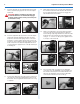
21. Legend LX Second Stage Service Manual Perform the venturi test: a. To test the venturi control, place the lever in the plus position. b. Depress the purge cover. You should get loud, run away freeflow. c. While the regulator is freeflowing, move the venturi lever to the minus position. The freeflow should stop abruptly. If it doesn’t stop abruptly, the crown orifice may be out too far. Try turning it in (clockwise) 1/8 of a turn and try again.
tion without excessive inhalation effort, freeflow, or “fluttering” of the second-stage diaphragm. When exhaling, there should be no fluttering or sticking of the exhalation valve. If any of these problems occur, refer to Table 1 - Troubleshooting.
Legend First Stage Service Manual Table 1 - Troubleshooting Guide SYMPTOM Leakage or freeflow from second stage POSSIBLE CAUSE 1. High first-stage intermediate pressure. (should be 135±5 psi) 1. Refer to first-stage Troubleshooting Guide. 2. LP seat (26) damaged or worn. 2. Replace LP seat. 3. Crown (21) adjusted incorrectly, lever set too high 3. Reset crown preliminary settings, and repeat Adjustment Procedures. 4. Lever (25) bent 4. Replace lever. 5. Crown (21) sealing surface damaged. 5.
Table 2 - Recommended Tool List PART NO. DESCRIPTION APPLICATION 111610 I.P.
Legend First Stage Service Manual Table 3 - Recommended Lubricants & Cleaners LUBRICANT / CLEANER Christo-Lube® MCG-111 APPLICATION All O-rings seals SOURCE Aqua Lung, PN 820466, or Lubrication Technologies 310 Morton Street Jackson, OH 45640 (800) 477-8704 CAUTION: Silicone rubber requires no lubrication or preservative treatment. DO NOT apply grease or spray to silicone rubber parts. Doing so may cause a chemical breakdown and premature deterioration of the material.
Procedure A Cleaning & Lubrication (All Aqua Lung Regulators) Brass and Stainless Steel Parts 1. Preclean in warm, soapy water* using a nylon bristle tooth brush. 2. Thoroughly clean parts in an ultrasonic cleaner filled with soapy water. If there are stubborn deposits, household white distilled vinegar (acetic acid) in an ultrasonic cleaner will work well. DO NOT place plastic, rubber, silicone or anodized aluminum parts in vinegar. 3.
Legend First Stage Service Manual Table 4 - Torque Specifications PART NUMBER DESCRIPTION / KEY NUMBER TORQUE AP2031 Retaining nut / 15 45±2 inch-lbs APF124563 Hose / 40 40±2 inch-lbs Table 5 - Test Bench Specifications TEST CONDITION ACCEPTABLE RANGE Leak Test Inlet 2,500-3,000 (±100) psig No leaks allowed Intermediate Pressure Inlet 2,500-3,000 (±100) psig 135±5 psi Intermediate Pressure Creep Inlet 2,500-3,000 (±100) psig 5 psi max between 5 to 15 seconds after cycling (purging)
Legend LX Exploded Parts Drawing Key # Part # ------ 900012 ------ 129080 1 ----- 129179 ------ 129171 2 ----- 129173 3 ----- 129187 4 ----- 129172 5 ----- 129132 6 ----- 129133 7 ----- 129145 8 ----- 129184 9 ----- 129155 ------ 129185 10 ---- 129154 11 ---- 109512 12 ---- 109438 ------ 104138 13 ---- 129174 14 ---- 104102 15 ---- AP2031 16 ---- 129148 17 ---- 820015 18 ---- AP1438 19 ---- 129138 20 ---- 820010 21 ---- AP2033 Description Overhaul Parts Kit Legend LX, Second Stage Only Retaining Ring,
2340 Cousteau Court, Vista, California 92083 www.aqualung.com Rev.