INSTALLATION AND OPERATING INSTRUCTIONS Gas Griddles MODELS: GGT-18i, -24i, -36i, -48i & MODELS: GGM-18i, -24i, -36i, 48i (US & Canadian units are convertible and are assembled for Natural Gas) (European units are not convertible and assembled for the appropriate gas) IMPORTANT FOR FUTURE REFERENCE Please complete this information and retain this manual for the life of the equipment. For Warranty Service and/or Parts, this information is required.
CAUTION: These models are designed, built, and sold for commercial use. If these models are positioned so the general public can use the equipment, make sure that cautions, warnings, and operating instructions are clearly posted near each unit so that anyone using the equipment will use it correctly and not injure themselves or harm the equipment. WARNING: Improper installation, adjustment, alteration, service or maintenance can cause property damage, injury or death.
IMMEDIATELY INSPECT FOR SHIPPING DAMAGE All containers should be examined for damage before and during unloading. The freight carrier has assumed responsibility for its safe transit and delivery. If equipment is received damaged, either apparent or concealed, a claim must be made with the delivering carrier. A) Apparent damage or loss must be noted on the freight bill at the time of delivery. It must then be signed by the carrier representative (Driver).
WARNING: Keep the appliance free & clear of all combustible substances. If gas odor is detected at any time, immediately shut unit down at the main shutoff valve. Do not permit any open flames in the area of the appliance. Immediately contact an authorized Service Agency or your local Gas Supplier for service. WARNING: Do not obstruct either the air inlet (underneath unit) or the ventilation air (back of unit). Provisions must be provided to provide an adequate air supply to the griddle.
Caution: DO NOT use an open flame to check for leaks. Check all gas piping for leaks with a soap and water solution before operating unit. THESE UNITS ARE SUITABLE FOR INSTALLATION ON NON-COMBUSTIBLE SURFACES ONLY. Noncombustible clearances: 0" sides (0 mm) 0" rear (0 mm) 4" floor (102mm) Do not obstruct the flow of combustion and ventilation air, under the unit by the legs or behind the unit by the flue. Adequate clearance for air openings into the combustion chamber is required.
5. Turn the burner knobs to "HI". If the burner does not ignite, promptly open the pilot valve more. If the pilot flame appears larger than necessary, turn it down and reset burner ignition. The pilot flame should be as small as possible but large enough to guarantee reliable ignition of the burners when the knobs are turned to "HI". Lighting main burner To light burner, turn knob to “max.” Then back off to the desired flame level. The range of adjustment is virtually infinite between high and off.
CLEANING / MAINTENANCE CAUTION: Use only non-abrasive cleaners. Abrasive cleaners could scratch the finish of your unit, marring it’s appearance and making it susceptible to dirt accumulation. Do Not use steel wool, other abrasive cleaners or cleaners/sanitizers containing chlorine, iodine, ammonia or bromine chemicals as these will deteriorate the stainless steel and glass material and shorten the life of the unit.
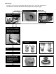
CONVERSION Instructions are for conversion from Natural Gas to Propane (L.P.) on all GGT & GGM models. The conversion should be done before connecting the unit to the gas supply. GGT Models 1. Remove the knobs and front panel. GGM Models Screw 2. Unscrew bolts and pilot valve, then remove the manifold. 2. Remove the supply tubes that go between the thermostats and the orifice bracket. 3. Unscrew and remove the orifice fittings from the valve.
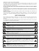
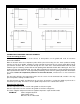
GGT CALIBRATION PROBE LOCATION CALIBRATION PROCEDURE FOR GGT GRIDDLES Locate the reading positions Make sure the griddle surface is clean. Grease or food particles on the griddle will result in inaccurate thermostat calibration. Mark the locations where the temperature probe will be placed for testing. See the sketch provided. Starting from the left side of the griddle, measure 8” to the right and 10-5/8” from the rear splash guard. With a felt tip pen mark this location.
If the temperature differential is large than 75ºF, there is probably a problem with your system. It may not be the thermostat. First make sure you thermostat probe is flat against the griddle plate and is making good contact. Dirt under the probe will cause inaccurate readings. Next make sure the thermostat bulb is held tightly in its holder. If you can pull the capillary tube and the bulb moves it is not held tight enough against the griddle plate.
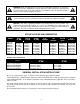
TROUBLESHOOTING GUIDE PROBLEM POSSIBLE CAUSE Thermostat is bad. Heat does not come on when thermostat is turned on. Pilot burner not lit. Gas valve is bad. Obstructed pilot orifice. Pilot burner will not light. Pilot gas turned off at automatic pilot. Automatic pilot valve is bad. Thermocouple is bad. Thermocouple is not hot enough. Pilot burner will not stay lit. Obstructed or wrong size pilot orifice. Gas supply is not purged of air. Air is blowing pilot light out. Automatic pilot valve is bad.
PARTS LISTS & EXPLODED VIEWS GGM GRIDDLES (EXPLODED VIEW) 12
GGM – PARTS LIST Item P/N Description Quan Item Weldment, Griddle GGM-18 Weldment, Griddle GGM-24 Weldment, Griddle GGM-36 Weldment, Griddle GGM-48 Body, 18" Firebox GGM Body, 24" Firebox GGM Body, 36" Firebox GGM Body, 48" Firebox GGM Tube, Pilot Supply GGM-18 Tube, Pilot Supply GGM-24/36/48 Pilot, Top Pilot, Broiler Support, Leg-18 Support, Leg-24 Support, Leg-36 Support, Leg-48 Side, Grease Chute Plug, 1/8 NPTM Side Panel, RH #8 X 3/8 Support, Burner-18 Support, Burner-24 Support, Burner-36 Support,
GGT GRIDDLES (EXPLODED VIEW) 14
GGT – PARTS LIST Item P/N Description Quan Item 218219-60 218220-60 218221-60 218222-60 2092614 81108-00 2065614 2068001 22030005 22030010 22030015 22030020 Weldment, Griddle, GGT -18 Weldment, Griddle, GGT -24 Weldment, Griddle, GGT -36 Weldment, Griddle, GGT -48 Elbow, 3/8CC X 3/8NPT, No Hood M/S Tr Hd Ph 6-32 x 1" Valve, Pilot GGT-18 Pilot Valve GGT-24/36/48 Support, Leg 18”, i-Line Support, Leg 24”, i-Line Support, Leg 36”, i-Line Support, Leg 48”, i-Line 1 1 1 1 Varies Varies 1 Varies 2 2 2 2 3
APW WYOTT EQUIPMENT LIMITED WARRANTY APW Wyott Foodservice Equipment Company warrants it's equipment against defects in materials and workmanship, subject to the following conditions: This warranty applies to the original owner only and is not assignable. Should any product fail to function in its intended manner under normal use within the limits defined in this warranty, at the option of APW Wyott such product will be repaired or replaced by APW Wyott or its Authorized Service Agency.