R INSTALLATION AND OPERATING INSTRUCTIONS Electric Griddles, Drop-In Style Models: EGD-48 & EGD-72 IMPORTANT FOR FUTURE REFERENCE Please complete this information and retain this manual for the life of the equipment. For Warranty Service and/or Parts, this information is required.
GENERAL INFORMATION THIS MANUAL SHOULD BE RETAINED FOR FUTURE REFERENCE CAUTION: These models are designed, built, and sold for commercial use.
SAFETY PRECAUTIONS Before installing and operating this equipment be sure everyone involved in its operation is fully trained and is aware of all precautions. Accidents and problems can result by a failure to follow fundamental rules and precautions. The following words and symbols, found in this manual, alert you to hazards to the operator, service personnel or the equipment. The words are defined as follows.
GENERAL INSTALLATION INSTRUCTIONS With all the large holes cut out, the smaller control panels drilled, and the stiffening angle welded into place the fixture is now ready to receive the griddle. 1. The manufacturer furnishes a gasket or seal that must be placed around the perimeter of the hole in the top as shown in Fig. 4. This gasket may be temporarily held in place with tape. Do not place the staple securing the gasket ends on or near a corner. 2. A number of clamps, such as the one shown in Fig.
Electrical Connections Terminal Box Location: The terminal boxes can be located at either the left front or right rear of the griddle. When shipped from the factory the device has the terminal box attached in the left front position. The box can be relocated to the alternate position by removing two screws. Loading: Electrical loadings of the griddles covered by this instruction are tabulated below. Fusing: Griddle is not fused and must be connected to a properly fused circuit.
the fabricator to easily vary this dimension up to 1 0 7/16 inches in increments of ¾ inch. 5. The minimum space between adjacent griddles must be 1 5/8 inch and between any other combination of drop in cooking equipment must be 1 inch. 6. 7. Electrical wiring crossing the tray slide is to be placed under the tray slide and not above it. The installer or servicer must put the electrical wiring near the control panel inside the wire guide before attaching the control panel to the fixture front.
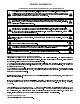
2. Load Griddle. After preheating, load griddle and cook according to recipe. Turn foods halfway through cooking time unless otherwise specified in recipe. Economy Hint: Turn griddle OFF (or to lowest thermostat setting) during idle periods. CAPACITIES MODEL EGD -48 MODEL EGD -72 QTY PER LOAD QTY PER LOAD APPROX HOURLY PRODUCTION APPROX HOURLY PRODUCTION BOTH MODELS COOKING TIME & TEMP MEATS - -oz. steaks, ) -oz. steaks, 1" thick) -oz. slices, 3/8 thick) 30 Ibs.
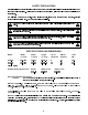
EGD-48 WIRING DIAGRAM L1 L2 L3
EGD-72 WIRING DIAGRAM Griddle (Bottom View) Thermostat Bulb ALTERNATE WIRING FOR TWO POWER SUPPLIES
PARTS LIST DROP-IN ELECTRIC GRIDDLES, EGD-48 & EGD-72 ITEM PART NUMBER DESCRIPTION 14397-25 14397-26 642567 -01 646378-03 646251-01 642578-01 642579-01 11260-35 647392-01 BOTTOM PANEL, EGD -48, R.H. 647395-01 BOTTOM PANEL, EGD -48, L.H.
APW WYOTT EQUIPMENT LIMITED WARRANTY APW Wyott Foodservice Equipment Company warrants it's equipment against defects in materials and workmanship, subject to the following conditions: This warranty applies to the original owner only and is not assignable. Should any product fail to function in its intended manner under normal use within the limits defined in this warranty, at the option of APW Wyott such product will be repaired or replaced by APW Wyott or its Authorized Service Agency.
R 24 Hour Toll Free Service Hot Line: 1-800-733-2203 APW WYOTT Foodservice Equipment Company P.O. Box 1829 Cheyenne, WY 82003 +1 (307) 634-5801 Phone +1 (800) 752-0863 Toll Free +1 (307) 637-8071 Fax www.apwwyott.