R INSTALLATION AND OPERATING INSTRUCTIONS Electric Griddles, Drop-In Style Models: EGD-1824, 1836, 1848, 2436, 2448, 2472 Please complete this information and retain this manual for the life of the equipment. For Warranty Service and/or Parts, this information is required. Model Number Serial Number Date Purchased CONTENTS 2 Installation Cutouts 7 Electrical Connections General 13 U.L.
U.L. CONDITIONS OF ACCEPTABILITY A. This equipment must be installed in an all metal fixture of steel or stainless steel construction, .078 inch thick minimum for the top and supporting frame. Side enclosure to be at least 22 MSG minimum thickness. B. A removable bottom enclosure must be provided under each drop-in unit and be made of metal construction of at least 22 MSG min.
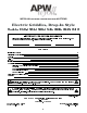
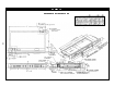
EGD-1824 REFERENCE NOTES ON PAGE 2
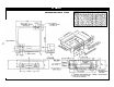
EGD-1836, EGD-2436 REFERENCE NOTES ON PAGE 2
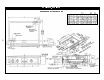
EGD-1848, EGD-2448 REFERENCE NOTES ON PAGE 2
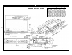
EGD-2472 REFERENCE NOTES ON PAGE 2
ELECTRICAL CONNECTIONS WARNING: Electrical and grounding connections must comply with the applicable portions of the national electrical code and/or other local electrical codes. WARNING: Disconnect electrical power supply and place a tag at the disconnect switch indicating that you are working on the circuit. Terminal Box Location. As indicated in Fig. 1, the terminal boxes can be located at either the left front or the right rear of the griddle.
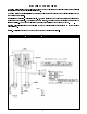
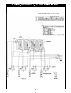
EGD-1836, 208/240/480VAC, 1 & 3 Phase (Wiring Diagram) 8
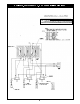
EGD-2436, 208/240/480VAC, 1 & 3 Phase (Wiring Diagram) 9
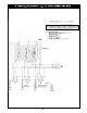
EGD-1848, 208/240/480VAC, 1 & 3 Phase (Wiring Diagram) 10
EGD-2448, 208/240/480VAC, 1 & 3 Phase (Wiring Diagram) 11
EGD-2472, 208/240/480VAC, 3 Phase (Wiring Diagram) 12
GENERAL Drop-In Griddles are designed to be installed into metal fixtures or fabricated tops. Fixture or top must be sufficiently rigid to support device weight without warping. Emphasis is on simplifying the layout and fabrication. These instructions covers all models. The floor plans for the griddles shows overall and other key dimensions of the device and their relationships to the fixture or top into which they will be installed. U.L.CONDITIONS OF ACCEPTABILITY: A.
1. Hobart furnishes a gasket or seal that must be placed around the perimeter of the hole in the top as shown in Fig. 3. This gasket may be temporarily held in place with tape. Do not place the staple securing the gasket ends on or near a corner. 2. A number of clamps, such as the one shown in Fig. 3, appear at intervals along the perimeter. Pull clamps outward so that the griddle frame clears them when it is dropped into place. 3.
OWNER'S INFORMATION CLEANING THE GRIDDLE AFTER INSTALLATION Before using the griddle for the first time, be sure to remove the factory-applied rust preventive compound. Add a mild detergent to hot water and wash the griddle well. Rinse with a clean, damp cloth and wipe dry. CONTROLS The heat of the griddle surface is controlled by turning the dial knobs (recessed in the front control pane!).
EGD-1824, EGD-1836 & EGD-1848 (Exploded View) 17 18 22 16 20 15 14 1 2 21 3 23 24 9 4 19 27 28 25 8 7 13 10 12 27 26 5 22 27 29 29 11 22 6
PARTS LIST ITEM 1 PART NUMBER DROP-IN ELECTRIC GRIDDLES, EGD-1824, -1836, -1848 DESCRIPTION 1439722 HEATING ELEMENT, 208 VOLT 1439723 HEATING ELEMENT, 240 VOLT 2 64256301 PRESSURE PLATE 3 64257301 BULB CLAMP ASSEMBLY 4 64634001 BAFFLE 5 64257801 TERMINAL BLOCK BOX 6 64257901 COVER 7 1126035 TERMINAL BLOCK 8 64258101 BOTTOM PANEL FOR -1824 64258201 BOTTOM PANEL FOR -1836 64258301 BOTTOM PANEL FOR -1848 64767903 BRACE ASSEMBLY FOR -1824 64767904 BRACE ASSEMBLY FOR -1836
EGD-2436, EGD-2448 & EGD-2472 (Exploded View) 10 12 13 9 8 20 21 1 23 11 24 22 22 28 30 29 27 5 28 30 25 7 22 27 26 6 4 18 17 16 22 2 3 19 15 14
PARTS LIST ITEM 1 PART NUMBER DROP-IN ELECTRIC GRIDDLES, EGD-2436, -2448, -2472 DESCRIPTION 1439725 HEATING ELEMENT, 208 VOLT 1439726 HEATING ELEMENT, 240 VOLT 2 64256701 PRESSURE PLATE 3 64257301 BULB CLAMP ASSEMBLY 4 64625100 BAFFLE 5 64257801 TERMINAL BLOCK BOX 6 64257901 COVER 7 1126035 8 64258202 TERMINAL BLOCK BOTTOM PANEL FOR -2436 64739201 1 EACH FOR -2448 64739401 1 EACH FOR -2448 FOR -2472 64258401 9 64767904 BRACE ASSEMBLY FOR -2436 FOR -2448 64306601 FOR -247
APW WYOTT EQUIPMENT LIMITED WARRANTY APW Wyott Foodservice Equipment Company warrants it's equipment against defects in materials and workmanship, subject to the following conditions: This warranty applies to the original owner only and is not assignable. Should any product fail to function in its intended manner under normal use within the limits defined in this warranty, at the option of APW Wyott such product will be repaired or replaced by APW Wyott or its Authorized Service Agency.