
Specifications

2
GENERAL INSTALLATION
General Cleaning Instructions
1. Always clean equipment thoroughly before first
use. (See general cleaning instructions.)
2. Check rating label for your model designation &
electrical rating.
3. Locate equipment on level counter and plug into
a grounded outlet so that the plug is accessible.
(See individual description for electrical loads.)
4. On units bearing the CE marking, the appliance
must be connected by an earthing cable to all
other units in the complete installation and then
to an independent earth connection.
1. NEVER clean any electrical unit by immersing it
in water. Unplug unit before surface cleaning.
2. Always clean equipment thoroughly before first
use. Clean unit daily. Except where noted on
charts: Use warm, soapy water. Mild cleaners &
PLASTIC scouring pads may be used to remove
baked-on food & water scale.
3. Unplug all units before cleaning or servicing. All
service should be performed by APW WYOTT
authorized service agency.
4. NEVER use a water jet to clean this unit.
GENERAL TROUBLESHOOTING
Always ask & check:
1. Is the unit plugged in?
2. Check circuit breaker.
3. Is power switch on?
4. Check rating label. Are you operating unit on
proper voltage?
5. If the supply cord is damaged, it should be
replaced by an identical supply cord by an
authorized service agency.
6. Is cooling fan clean and free from obstruction?
If the above checks out, and you still have
problems, call anAPW WYOTT authorized agency.
GENERAL INFORMATION
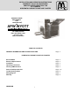
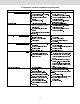
BT-15 SPECIFICATIONS
PLEASE READ PAGE 2 - "GENERAL
INFORMATION," BEFORE YOU CONTINUE.
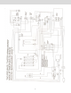
Electrical Information - Models BT-15 Twist Lock
or Pin Sleeve.
Each unit is equipped witha6foot,Pin&sleeve
plug, 30A 208-240V or Twist lock.
Model Number BT-15
Overall
Electrical 208V. 4150 W. 20.0A.60Hz
240V. 4150 W. 17.3A.60Hz
230V. 3890 W. 16.9A.50Hz
Net/Shipping 8lbs/65lbs (26.4kg/29.5kg)
Dimensions (47 cm x 46.6 cm x 54 cm)
Weight
INSTALLATION - BT SERIES
B. ASSEMBLY
NOTE:
CAUTION:
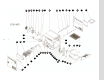
A. UNPACK UNIT
1.Remove unit from shipping carton, unwrap
loose parts and remove any packing tape.
2.Refer to the list below and account for the
following parts:
a. (4) Legs - wrapped, internal package
b. Bread Slide - shipped in place
c. Bread Drawer - shipped in place
d. Reflector/Crumb Tray shipped in place
e. Superfeeder - wrapped, internal package
f. Instruction Manual-wrapped, internal
package
g.Feeder support - wrapped, internal
wrapped
CAUTION: DO NOT OPERATE THE
TOASTER WITHOUT THE LEGS INSTALLED.
1. Refer to the illustration and check the
Reflector / Crumb Tray is in the right position.
DO NOT OPERATE THE T O A S T E R
WITHOUT THE REFLECTOR / CRUMB TRAY IN
POSITION UNDER THE CONVEYOR CHAIN.
2. Check that the bread drawer is positioned flat
on toaster base and pushed to the rear until it
stops. (Note: Bread Drawer is installed or
removed by lifting the front handle at an angle
so that the rear edge of the drawer slides under
the two front internal studs on right and left
sides of toaster walls.) Check that the Bread
Slide is situated internally so that the "tabs" on
each side are resting behind the two rear
internal studs on right and left sides of toaster
walls. The front edge of the Bread Slide rests on
top of the two front internal studs on right and
left sides of the toaster walls. The Bread Slide
should be covering the rear portion of the bread
drawer.
3. Attach the superfeeder on the rod and pins
located in front of the conveyor belt.