
Operating instructions


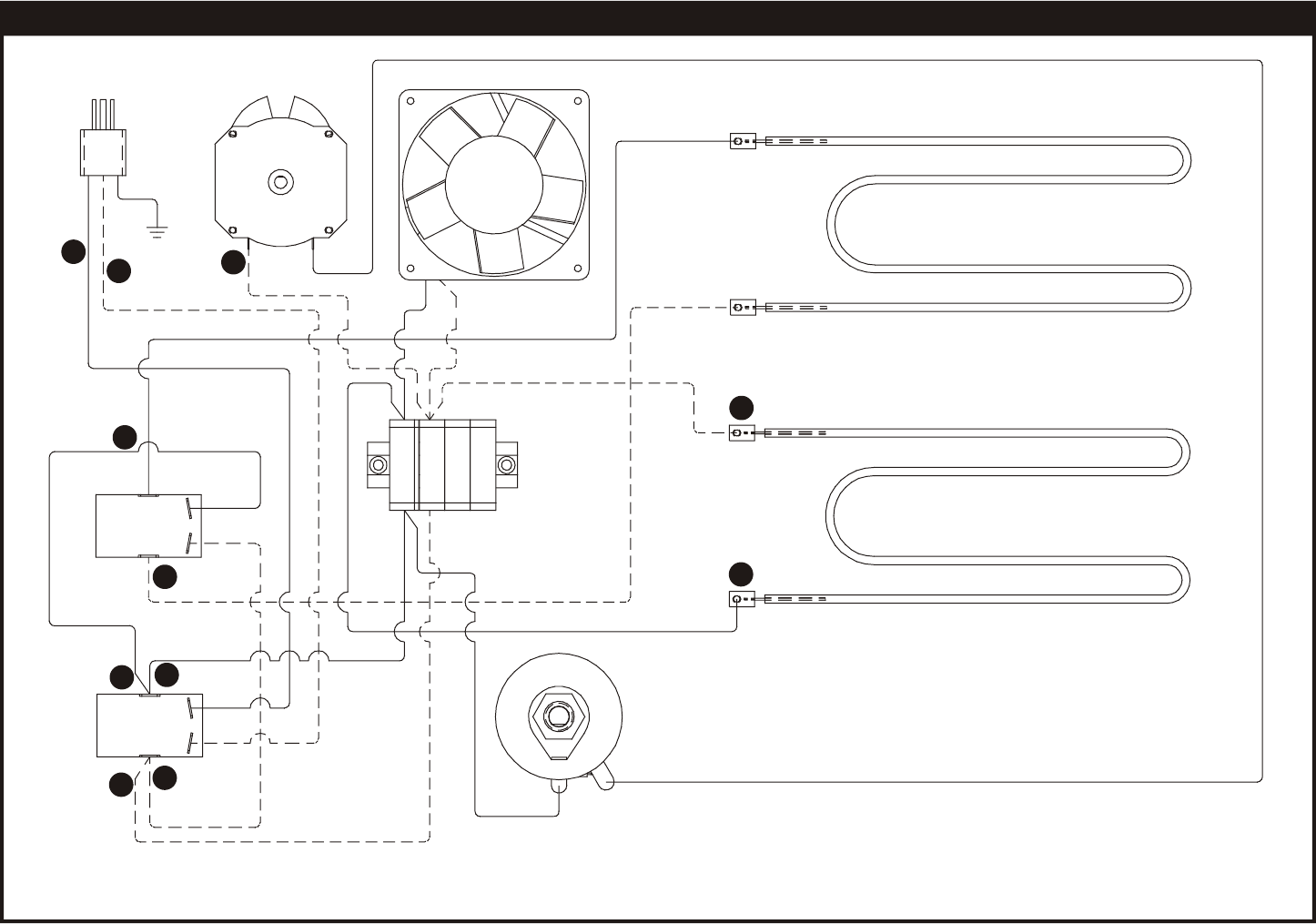
9. WIRING DIAGRAM9. WIRING DIAGRAM
1
2
3
4
5
6
7
8
9
10
11
ON/OFF SWITCH
STANDBY SWITCH
CORD SET
DRIVE MOTOR
COOLING FAN
TOP ELEMENT
BOTTOM ELEMENT
TERMINAL BLOCK
RHEOSTAT
L1
L2
GND
BLUE
BLACK
IMPORTANT NOTICE: The information contained in this section of the manual is intended for individuals possessing backgrounds of electrical and
mechanical experience, such as an authorized APW Wyott service technician. APW or the seller cannot be responsible for the interpretation of this
information, nor can it assume any liability in connection with its use.
10