
User's Manual
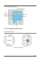
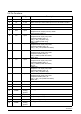
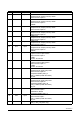

Table Of Contents

Version1.4
20 GND Input
Analog ground
21 P8 Input
• GPIO: P8
• Keyboard scan output (column): KSO0
• A/D converter input 27
22 P14 Input
• GPIO: P14
• Keyboard scan output (column): KSO6
• A/D converter input 21
• PWM2
23 P10 Input
• GPIO: P10
• Keyboard scan output (column): KSO2
• A/D converter input 25
24 P9 Input
• GPIO: P9
• Keyboard scan output (column): KSO1
• A/D converter input 26
25 P11 Input
• GPIO: P11
• Keyboard scan output (column): KSO3
• A/D converter input 24
26 P12 Input
• GPIO: P12
• Keyboard scan output (column): KSO4
• A/D converter input 23
27 P13 Input
• GPIO: P13
• Keyboard scan output (column): KSO5
• A/D converter input 22
• PWM3
28 P28 Input
• GPIO: P28
• Optical control output: QOC2
• A/D converter input 11
• LED1
Current: 16 mA sink
29 P29 Input
• GPIO: P29
• Optical control output: QOC3
• A/D converter input 10
• LED2
Current: 16 mA sink
30 P0 Input
• GPIO: P0
• Keyboard scan input (row): KSI0
• A/D converter input 29
• Peripheral UART: puart_tx
• SPI_1: MOSI (master and slave)
• IR_RX
31 P1 Input
• GPIO: P1
• Keyboard scan input (row): KSI1
• A/D converter input 28
• Peripheral UART: puart_rts
• SPI_1: MISO (master and slave)
• IR_TX
32 P34 Input
• GPIO: P34
• A/D converter input 5
• Quadrature: QDY0
• Peripheral UART: puart_rx
33 P38 Input
• GPIO: P38
• A/D converter input 1
• SPI_1: MOSI (master and slave)
• IR_TX
34 P39 Input
• GPIO: P39
• SPI_1: SPI_CS (slave only)