
User's Manual
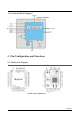
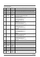
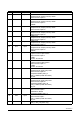
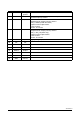

Table Of Contents

Version1.4
2.2 Pin Functions
Pin Name IO Type Description
1 RX I UART serial input. Serial data input for the HCI UART interface
2 TX O, PU UART serial input. Serial data input for the HCI UART interface
3 RTS O, PU RTS for HCI UART interface
4 CTS I, PU CTS for HCI UART interface:
5 P16 Input
• GPIO: P16
• Keyboard scan output (column): KSO8
• A/D converter input 19
6 P2 Input
• GPIO: P2
• Keyboard scan input (row): KSI2
• Peripheral UART: puart_rx
• SPI_1: SPI_CS (slave only)
• SPI_1: MOSI (master only)
7 P3 Input
• GPIO: P3
• Keyboard scan input (row): KSI3
• Peripheral UART: puart_cts
• SPI_1: SPI_CLK (master and slave)
8 P5 Input
• GPIO: P5
• Keyboard scan input (row): KSI5
• Peripheral UART: puart_tx
• SPI_1: MISO (master and slave)
• BSC: SDA
9 P4 Input
• GPIO: P4
• Keyboard scan input (row): KSI4
• Peripheral UART: puart_rx
• SPI_1: MOSI (master and slave)
• IR_TX
10 P6 Input
• GPIO: P6
• Keyboard can input (row): KSI6
• Peripheral UART: puart_rts
• SPI_1: SPI_CS (slave only)
11 P7 Input
• GPIO: P7
• Keyboard scan input (row): KSI7
• Peripheral UART: puart_cts
• SPI_1: SPI_CLK (master and slave)
• BSC: SCL
12 SF_WP Input
Flash WP port
13 NC NC
NC
14 GND Ground
Ground
15 AGND Analog
ground
Analog ground
16 MICBIAS Input
Microphone bias supply
17 MICP Input
Microphone positive input
18 MICN Input
Microphone negative input
19 AGND Analog
ground
Analog ground